 English
 русский
 Tiếng Việt
 Español

A single-phase motor hums but refuses to turn over. A rooftop air-conditioning compressor trips on thermal overload every hot afternoon. A switch-mode power supply that ran reliably for three years fails during the first heat wave of the season. Three different failures, one common first question: was the capacitor sized correctly?
Here is the short answer: a capacitor sizing chart matches application demand — motor power, line voltage, duty cycle — to capacitor parameters such as capacitance, voltage rating, ripple capability, and lifetime. The chart is a screening tool, not a substitute for the motor nameplate, the original component marking, or the manufacturer's datasheet. Read it correctly, and it prevents the most common field failures. Read it without context, and it produces the overheating, premature aging, and repeat callbacks it was meant to eliminate.
What a Capacitor Sizing Chart Really Shows
Most published capacitor sizing charts were written for single-phase motors and HVAC equipment. In that world the selection problem is compact: motor horsepower and supply voltage point to a microfarad range for a start capacitor or a run capacitor, and the chart is essentially a lookup table.
For aluminum electrolytic capacitors used in power electronics, the chart takes a different shape. Inverters, variable-frequency drives, welding equipment, and charging stations still require a capacitance and voltage check, but ripple current, equivalent series resistance (ESR), operating temperature, and expected lifetime must be read alongside the microfarad value. Skipping those columns is the most common reason a capacitor that looks correctly sized on paper fails early in service.
Start With Capacitance: the Microfarad Value
Capacitance, expressed in microfarads (µF), is the first column on any sizing chart because it determines the amount of phase shift or energy storage the circuit receives. In a permanent-split-capacitor motor, the run capacitor remains in the circuit continuously and sets the phase angle between the start and run windings. Too little capacitance reduces starting torque and can cause the motor to stall; too much raises running current and accelerates winding heating. A start capacitor, switched out by a centrifugal switch or relay once the motor approaches full speed, is sized for the brief inrush interval at startup.
The replacement rule is deliberately conservative: keep the run capacitance within roughly ±10 percent of the original value, and do not install a start capacitor that is substantially larger than the original unless the motor manufacturer permits it. On the chart, that means reading the row closest to the nameplate horsepower, confirming the result against the original capacitor marking, and resisting the temptation to "upgrade" a microfarad value for extra torque.
Voltage Rating: the Margin That Protects the Dielectric
Voltage rating is the second mandatory check. The rule is simple and non-negotiable: a replacement capacitor must carry a voltage rating at or above the original. A 440 VAC capacitor can replace a 370 VAC unit in HVAC duty; the reverse is not acceptable. Motor capacitor charts separate columns by line voltage — 115 V, 230 V, 460 V — and the selected capacitor class must cover the nominal voltage plus the typical service tolerance seen at the installation site.
The same principle applies to DC aluminum electrolytics, but with the addition of derating. Operating a 50 V capacitor at 48 V leaves little room for ripple voltage and line transients; a 63 V or 80 V part provides a safety margin that directly improves reliability. Many manufacturers recommend running at 80 percent or less of rated voltage as a practical trade-off between case size and lifetime. Higher applied voltage increases leakage current and accelerates electrolyte loss, which is why voltage overstress shows up as premature end-of-life rather than immediate failure.
Application-Specific Rows on the Chart
The chart is only as useful as the application row you select. Motor starting, HVAC operation, and industrial power processing each stress a capacitor differently, and the same microfarad value means different things in each context.
Single-Phase Motors and HVAC Equipment
Motor sizing charts pair horsepower with capacitance ranges. The table below gives typical starting points for the most common single-phase motor ratings; verify every value against the motor nameplate and the original capacitor before ordering a replacement.
| Motor rating | Typical run capacitance (µF) | Typical start capacitance (µF) |
|---|---|---|
| 1/4 HP | 4–5 | 100–150 |
| 1/2 HP | 5–7.5 | 130–180 |
| 1 HP | 10–15 | 200–270 |
| 2 HP | 20–30 | 300–400 |
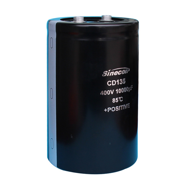
For motor-start duty, the capacitor must handle a heavy inrush pulse without overheating its winding. The CD60 standard screw-terminal motor-starting capacitor is built for exactly this requirement, with a rugged terminal interface that suits industrial and agricultural equipment. For air-conditioning and refrigeration, the sizing equation changes because run hours and ambient heat dominate. A general-purpose part with the same microfarad value may pass the chart check and still fail within one season; a CD13L long-life screw-terminal capacitor for air-conditioners factors continuous operation into its lifetime rating.
 CD13L Long Life Screw Terminal Aluminum Electrolytic Capacitors For Air ConditioNantong Xingchen Electron Co., Ltd. is China Wholesale CD13L Long Life Screw Terminal Aluminum Electrolytic Capacitors For Air Conditione...View Product →
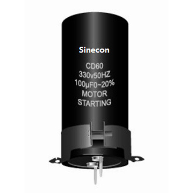 CD60 Standard Screw Terminal Aluminum Electrolytic Capacitors For Motor StartingNantong Xingchen Electron Co., Ltd. is China Wholesale CD60 Standard Screw Terminal Aluminum Electrolytic Capacitors For Motor Starting S...View Product →
Power Electronics and Industrial Drives
Inverters, servo drives, welding equipment, and charging stations do not use a horsepower-to-microfarad lookup. The design input is ripple current, and the most important column on the chart becomes the allowable ripple at the expected ambient temperature. A capacitor with the perfect capacitance and voltage rating but insufficient ripple capability will overheat internally, vent, and fail — often at a fraction of the intended service life.
Designers facing this trade-off typically choose a CD293 high-ripple standard snap-in capacitor, then verify ESR at the switching frequency. The chart answers "how many microfarads"; the ripple and ESR data answer "how hard this part can actually work." Treat the two questions as separate steps, because answering only the first is how improperly sized capacitors reach production.
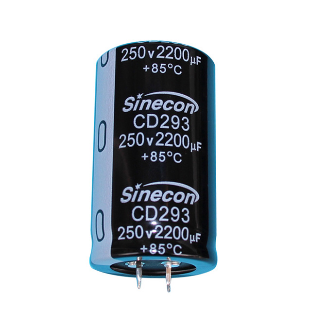 CD293 High Ripple Standard Snap-In Aluminum Electrolytic Capacitor Suppliers, CoNantong Xingchen Electron Co., Ltd. is China Wholesale CD293 High Ripple Standard Snap-In Aluminum Electrolytic Capacitor Suppliers and C...View Product →
Beyond the Chart: Ripple Current, ESR, and Temperature
Three parameters separate a successful selection from a premature field failure: ripple current, ESR, and temperature. They work as a chain. Ripple current flows through ESR and produces heat inside the capacitor body; the heat raises the core temperature; and for aluminum electrolytic capacitors, every 10 °C increase above the rated ambient temperature cuts typical lifetime by roughly half.
A sizing chart that lists only capacitance and voltage is therefore incomplete for power electronics. This is why understanding how ESR affects aluminum electrolytic capacitor performance matters more than the microfarad value in many high-frequency designs. Case size is part of the same thermal story: a larger can dissipates heat across a bigger surface and usually carries a higher ripple rating for the same capacitance. When the chart includes case diameter and length, treat the row as a thermal specification rather than a mechanical convenience.
Tolerance, Case Size, and Manufacturer Data
Aluminum electrolytic capacitors are commonly marked with a ±20 percent capacitance tolerance as the default class, with some series offering ±10 percent. The tolerance matters at the moment of replacement: a 10 µF part at the negative tolerance limit measures 8 µF, which may sit outside the motor's acceptable range even though the printed marking appears correct. Match the original capacitance and tolerance class, not just the nominal value.
The same discipline applies to the full set of selection factors. The factors to consider when selecting radial electrolytic capacitors — operating temperature range, shelf life, ripple current at the application frequency — remain valid for through-hole designs, while high-power rails usually require screw-terminal or snap-in packaging. A practical workflow looks like this:
- Record the application voltage plus the original capacitance, tolerance, and case size.
- Identify the worst-case ambient temperature and the ripple current at the operating frequency.
- Select a capacitor with a voltage rating at or above the original, ideally with derating headroom.
- Compare lifetime at the actual ripple and temperature using manufacturer data, not the chart alone.
- Verify terminal style and mounting constraints, then cross-check the datasheet before prototyping or batch ordering.
For high-power rails, the screw terminal capacitor selection guide covers type-specific decisions — terminal style, mounting torque, and cooling considerations — that never appear on a motor capacitor chart.
Sizing Charts and the Bottom Line
A capacitor sizing chart is a fast screening tool. It answers the first three questions — capacitance, voltage, and application class — and it says nothing about ripple capability, thermal margin, or lifetime. The correct order is always the same: use the chart to build a shortlist, read the nameplate and original marking to confirm the requirement, and check the manufacturer's datasheet to verify the part can survive the actual operating point.
In our own work as a manufacturer of aluminum electrolytic capacitors, the most common warranty returns trace back to one of these omissions: a voltage rating too close to the rail, a ripple current underestimated at maximum load, or a capacitor selected for cost instead of temperature. Each of those cases looked correct on a chart. None of them survived contact with real operating conditions. Choose the part that fits the chart, then choose the one that fits the datasheet.