 English
 русский
 Tiếng Việt
 Español

Power Electronics / Component Guide
A closer look at the quiet workhorse behind every stable power supply — how aluminum capacitors shape voltage, absorb transients, and keep motors running true.
What Are Aluminum Capacitors Used For in Power Supply Circuits?
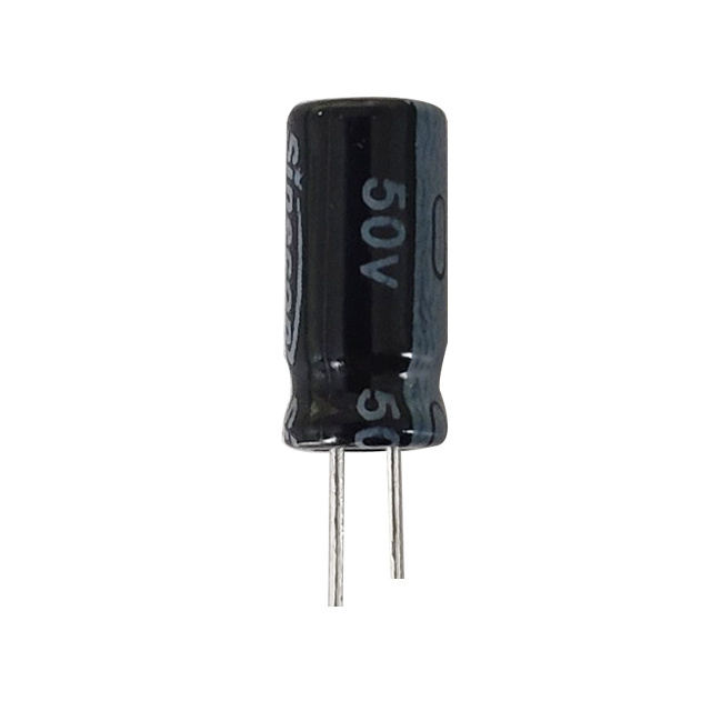
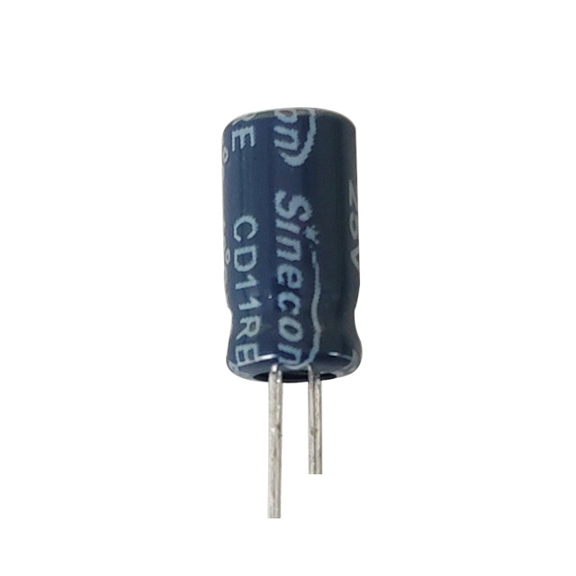
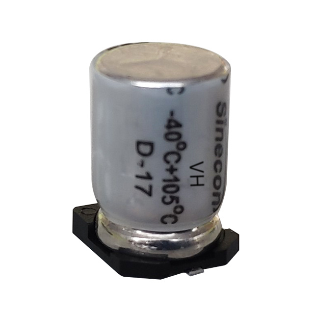
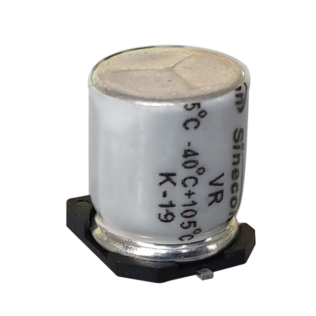
In power supply circuits, aluminum electrolytic capacitors are primarily used to smooth rectified DC voltage, filter out ripple and noise, and store energy that stabilizes output under sudden load changes. Because they offer high capacitance values in a relatively compact and low-cost package, they sit at the input and output stages of nearly every AC-to-DC power supply, from small phone chargers to industrial motor drives. Their job is simple to describe but critical in practice: absorb the peaks and fill in the valleys of a pulsing voltage so downstream electronics receive a clean, steady supply.
Unlike ceramic or film capacitors, aluminum electrolytics can reach capacitance values from a few microfarads up to tens of thousands of microfarads, which makes them the default choice whenever a circuit needs bulk energy storage rather than high-frequency precision filtering. This is why you will find them clustered around bridge rectifiers, voltage regulators, and switching converters rather than in signal-timing or RF circuits.
Smoothing and Filtering Rectified DC Voltage
When AC voltage passes through a bridge rectifier, the result is not a flat DC line but a series of pulsing humps. An aluminum capacitor placed immediately after the rectifier charges during each voltage peak and discharges during the gaps, filling in the troughs so the output voltage stays close to a constant level. This process is called ripple smoothing, and the size of the capacitor directly determines how flat the resulting DC waveform is.
aluminum electrolytic capacitor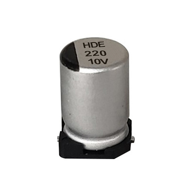
A larger capacitance value reduces ripple amplitude but increases physical size and cost, so designers balance the two based on how sensitive the downstream circuit is to voltage fluctuation. Linear power supplies with tight regulation requirements often use larger bulk capacitors, while switching supplies rely on smaller values paired with fast feedback control.
Why Ripple Matters
Excessive ripple can cause audible hum in audio equipment, flicker in LED drivers, and instability in voltage-regulated circuits. Keeping ripple within a target range, often under 1–2% of the nominal DC voltage for sensitive electronics, is one of the main reasons aluminum capacitors remain standard components in power design.
A capacitor that cannot handle its ripple current will run hot long before it visibly fails — heat, not voltage, is usually the real enemy.
Energy Storage and Load Transient Support
Beyond smoothing, aluminum capacitors act as a local energy reserve. When a load suddenly draws more current, such as a motor starting or a processor spiking to full load, the capacitor supplies the extra charge instantly while the power supply's regulation circuitry catches up. Without this buffer, voltage would sag momentarily, potentially causing resets, glitches, or torque loss in motors.
This transient-response role is why aluminum capacitors are placed close to switching regulators, motor drivers, and amplifier output stages rather than only at the main input filter. Each stage of a power system typically has its own local capacitor sized for the current demands of that specific load.
Placing a capacitor physically close to the load it supports reduces parasitic inductance in the connecting traces, which improves how quickly it can respond to a current spike.
Common Applications Across Power Circuit Types
Aluminum capacitors appear across a wide range of power electronics, each application relying on a slightly different balance of capacitance, voltage rating, and ripple current handling. The table below summarizes typical use cases.
| Circuit Type | Primary Function | Typical Capacitance Range |
|---|---|---|
| AC-DC input rectification | Bulk energy storage, ripple reduction | 100µF – 10,000µF |
| Switching power supply output | Output smoothing, transient response | 10µF – 1,000µF |
| Motor drive DC bus | Energy buffering during load changes | 470µF – 20,000µF |
| LED driver circuits | Flicker reduction, current smoothing | 10µF – 470µF |
| Audio amplifier power stage | Decoupling, hum reduction | 1,000µF – 10,000µF |
Key Specifications That Determine Performance
Selecting the right aluminum capacitor for a power circuit involves more than picking a capacitance value. Several parameters interact to determine how well the component will perform and how long it will last in service.
Voltage Rating
The rated voltage must exceed the maximum voltage the capacitor will see, including transients, with a safety margin typically of 20% or more. Operating too close to the rated voltage accelerates dielectric aging and shortens service life.
Ripple Current Rating
Every aluminum capacitor has a maximum ripple current it can handle before internal heating shortens its lifespan. Exceeding the ripple current rating is one of the most common causes of premature capacitor failure in power supplies, since the resulting heat dries out the electrolyte faster than the rated temperature curve predicts.
Running a capacitor beyond its rated ripple current does not usually cause instant failure — it quietly shortens lifespan, often by years, before symptoms appear.
Equivalent Series Resistance (ESR)
Lower ESR means less internal power loss and less self-heating during operation. High-frequency switching supplies generally require low-ESR aluminum capacitors to keep ripple voltage and thermal stress under control.
Temperature Rating and Lifespan
Most standard aluminum capacitors are rated at 85°C or 105°C, with rated life following a rule of thumb where lifespan roughly doubles for every 10°C reduction in operating temperature. A capacitor rated for 2,000 hours at 105°C may last well over 10,000 hours if it consistently operates at 65–75°C.
How to Test an Aluminum Capacitor Before Replacing It
Before assuming a power supply fault is caused by a bad capacitor, it helps to confirm the diagnosis with a simple bench test. Knowing how to read a capacitor with multimeter tools is a practical skill for anyone servicing power supplies, motor start circuits, or HVAC equipment.
Always discharge a capacitor safely through a resistor before testing. Residual charge in a large aluminum capacitor can deliver a painful or dangerous shock even after power is switched off.
Checking Capacitor With Ohm Meter
A quick resistance-based check can reveal an obviously shorted or open capacitor. After discharging the capacitor safely, set the meter to a high resistance range and touch the probes to the terminals. A healthy capacitor will show resistance climbing steadily toward infinity as it charges from the meter's internal voltage; a reading stuck at zero ohms suggests a short, while a reading that never moves at all suggests an open circuit.
- Power down the circuit and discharge the capacitor through a resistor.
- Set the multimeter to its resistance or capacitance test mode.
- Connect the probes to the correct polarity terminals.
- Watch the reading trend upward rather than staying fixed.
- Compare the measured capacitance, if available, against the printed rating.
How to Check a Capacitor Using Digital Multimeter Capacitance Mode
Most modern digital multimeters include a dedicated capacitance mode marked with a "µF" or capacitor symbol on the dial. This method is more precise than the resistance trick because it gives an actual microfarad reading. A capacitor reading below roughly 70% of its printed capacitance value is generally considered degraded and worth replacing, especially in power supply or motor-start applications where full capacitance is needed to deliver rated performance.
For polarized aluminum electrolytics, always confirm terminal polarity before testing, since reverse voltage from the meter can produce inaccurate readings or, in poor-quality meters, stress the capacitor further.
If the measured capacitance falls within about 10–15% of the printed rating and ESR is low, the capacitor can generally be trusted back into service.
Selecting the Correct AC Capacitor Size for Motor and HVAC Circuits
Aluminum capacitors also play a major role outside of low-voltage electronics, particularly in motor-start and motor-run applications such as air conditioning compressors, fans, and pumps. Choosing the correct ac capacitor size is essential, since an undersized capacitor fails to provide enough starting torque while an oversized one can overheat the motor windings.
Sizing is generally based on the motor's horsepower and voltage rating rather than a fixed formula, and the microfarad value along with the voltage rating is typically printed directly on the original capacitor or listed in the equipment's service manual. When replacing a failed unit, matching both the capacitance and voltage rating as closely as possible is more important than matching physical size or case shape.
| Motor Load | Typical Capacitor Type | Common Voltage Rating |
|---|---|---|
| Small fan or pump motor | Run capacitor | 370V or 440V |
| Compressor motor | Start/run dual capacitor | 370V or 440V |
| Single-phase HVAC blower | Run capacitor | 370V |
Signs an Aluminum Capacitor Is Failing
Visual and electrical symptoms usually appear before a total failure occurs. Recognizing these early can prevent secondary damage to the rest of the power circuit.
- Bulging or domed top vent on the capacitor case.
- Visible electrolyte leakage around the base or on the circuit board.
- Measured capacitance significantly lower than the rated value.
- Rising ESR readings on a dedicated ESR meter.
- Circuit symptoms such as flickering, humming, or intermittent shutdowns.
Motors that struggle to start, HVAC compressors that hum without spinning up, or power supplies that produce excessive ripple noise are all common downstream indicators that trace back to a degraded aluminum capacitor.
Aluminum vs Film vs Ceramic Capacitors in Power Circuits
Aluminum capacitors are not always the right choice. Film capacitors offer better stability and lower losses at high frequency but cost more per microfarad, while ceramic capacitors excel at high-frequency decoupling but cannot match aluminum's bulk capacitance in a small footprint.
| Type | Strength | Best Used For |
|---|---|---|
| Aluminum electrolytic | High capacitance, low cost | Bulk filtering, energy storage |
| Film | Stability, low loss | AC coupling, motor run applications |
| Ceramic | High-frequency response | Decoupling, noise suppression |
Practical Takeaways for Power Circuit Design
Aluminum capacitors remain the backbone of power supply filtering because they deliver high capacitance at a manageable cost and size. Their core roles, smoothing rectified voltage, buffering transient loads, and supporting stable motor operation, make them essential across consumer electronics, industrial drives, and HVAC systems alike.
Matching voltage rating, ripple current capability, and temperature rating to the actual operating conditions is the single most effective way to extend service life. And when a circuit starts showing symptoms of instability, a simple test with a multimeter, whether reading resistance trend, checking capacitor with ohm meter techniques, or using a digital multimeter's dedicated capacitance mode, is usually enough to confirm whether the aluminum capacitor is the root cause before replacing it with a correctly sized part.