 English
 русский
 Tiếng Việt
 Español

Component Engineering · Design Comparison
Why Electrolytic Capacitors
Still Win the Capacitance Race
Ceramic and film capacitors offer precision and longevity — but when a circuit needs real bulk capacitance, nothing matches the density of an electrolytic. Here's the physics, the trade-offs, and the practical guidance behind that choice.
Direct Answer: Why Electrolytic Capacitors Dominate High-Capacitance Roles
Electrolytic capacitors are preferred for high-capacitance applications because they deliver far more capacitance per dollar and per cubic millimeter than ceramic or film capacitors. A single electrolytic capacitor can reach values from a few microfarads up to tens of thousands of microfarads in a modestly sized cylindrical package, while a ceramic capacitor of the same physical footprint typically tops out in the single-digit microfarad range, and a film capacitor rarely exceeds a few dozen microfarads before becoming impractically large.
This capacitance density comes from the electrolytic construction itself: a thin oxide layer grown on an etched aluminum or tantalum foil acts as the dielectric, paired with a liquid or solid electrolyte that serves as the second "plate." That combination allows an extremely large effective surface area to be packed into a small volume — something ceramic and film dielectrics simply cannot replicate at equivalent size and cost.
Capacitance density isn't a marginal advantage — it's the entire reason bulk energy storage is even feasible in a component the size of a fingertip.
The Physics Behind the Capacitance Advantage
Capacitance is proportional to the surface area of the plates and inversely proportional to the distance between them. Electrolytic capacitors exploit both variables aggressively. Manufacturers etch the aluminum foil used in the anode to create a rough, porous surface, which can multiply the effective surface area by a factor of 50 to 100 compared to a flat sheet. At the same time, the anodized oxide layer that forms the dielectric is only a few nanometers thick — far thinner than the ceramic or polymer film layers used in other capacitor types. The result is a dielectric with an extremely small plate separation and enormous surface area, which together produce capacitance values that would require an unreasonably large ceramic or film capacitor to match.
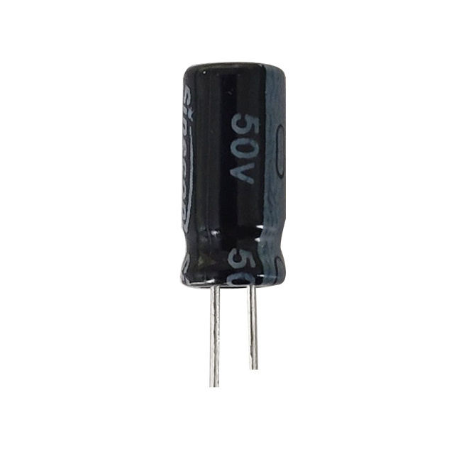
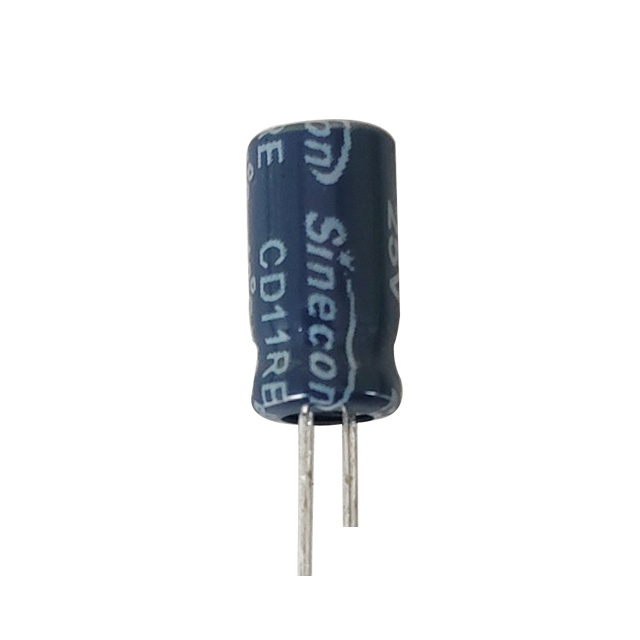
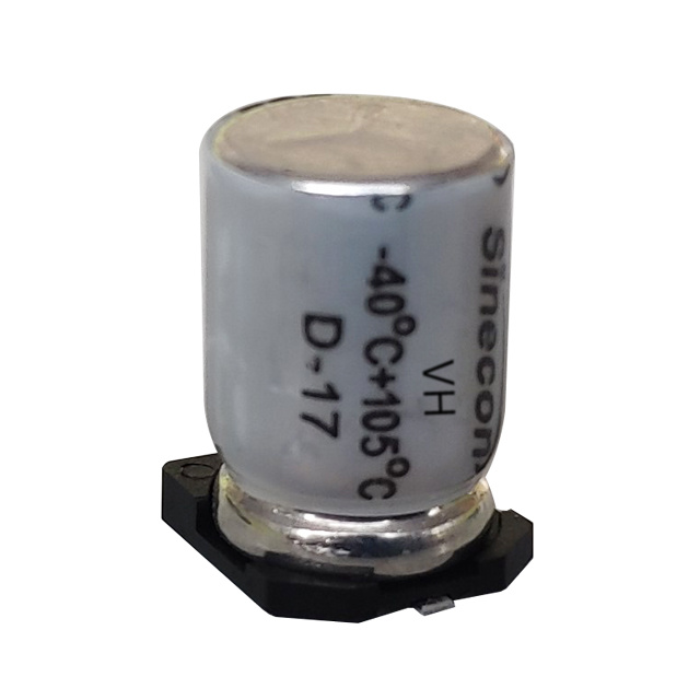
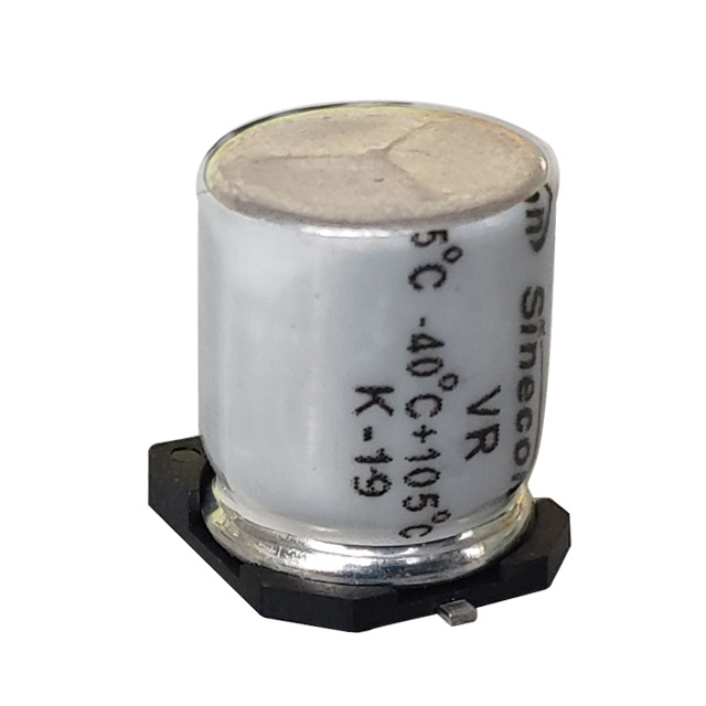
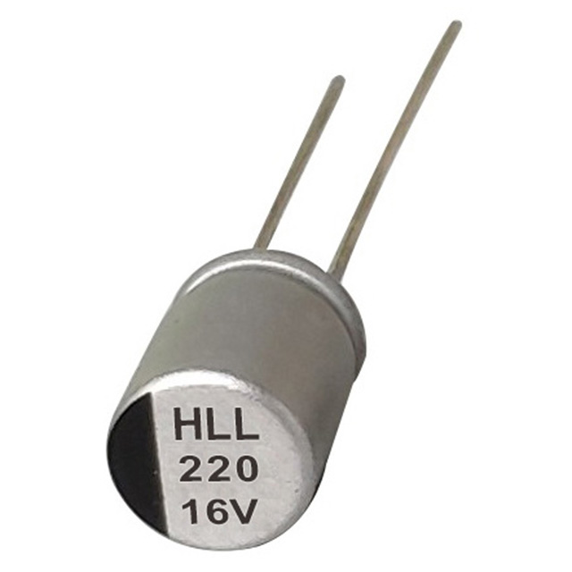
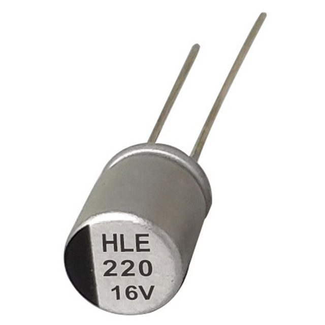
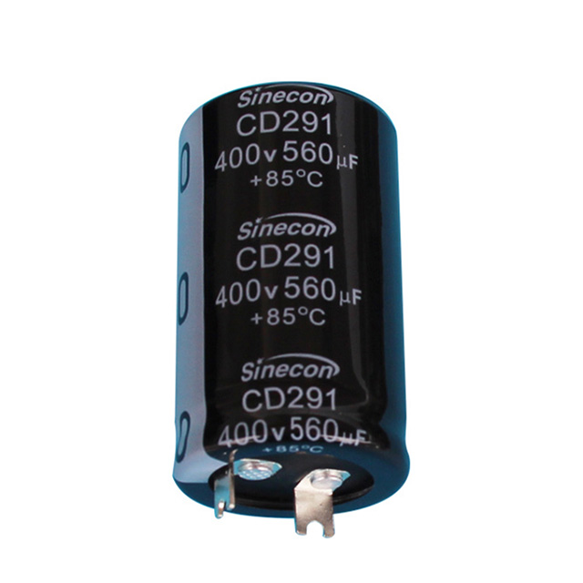
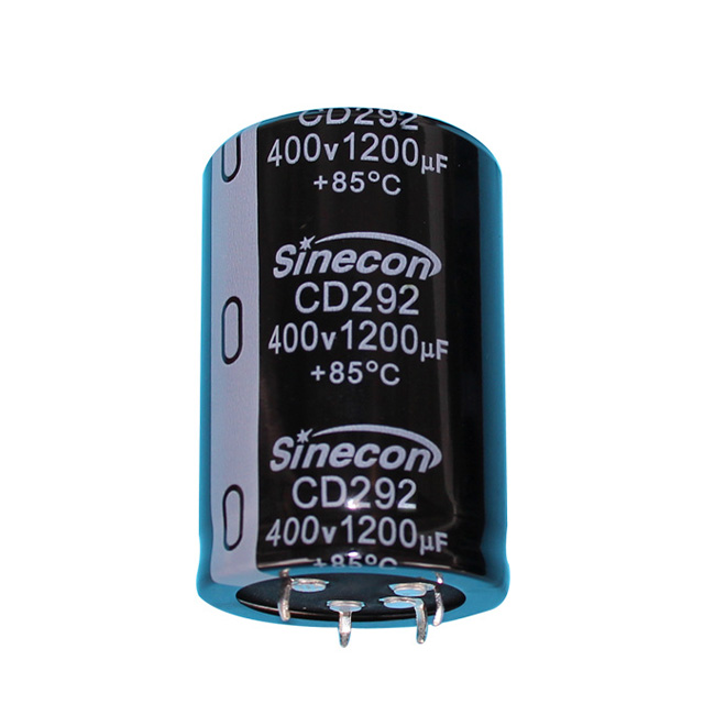
Electrolytic capacitors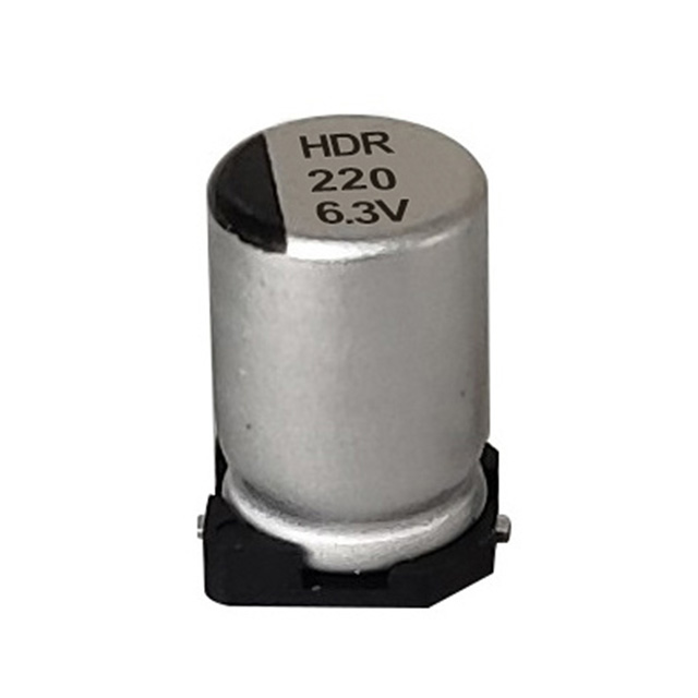
Ceramic capacitors, by contrast, rely on stacking many thin layers of ceramic dielectric between metal electrodes (multilayer ceramic capacitors, or MLCCs). While this stacking technique has improved capacitance density over the decades, physical and cost constraints still limit practical MLCCs to roughly 100 µF at most in commonly available sizes, and even then, capacitance drops significantly under DC bias voltage — a phenomenon known as voltage coefficient of capacitance, which is far less pronounced in electrolytic types.
Side-by-Side Comparison of Capacitor Technologies
Each capacitor family brings a different balance of capacitance, size, stability, and cost. The table below summarizes how electrolytic, ceramic, and film capacitors compare across the factors that matter most when selecting a component for a high-capacitance role.
| Property | Electrolytic | Ceramic (MLCC) | Film |
|---|---|---|---|
| Typical Capacitance Range | 1 µF – 100,000 µF | 1 pF – 100 µF | 1 nF – 30 µF |
| Cost per µF (large values) | Low | High | Very High |
| Polarity | Polarized (most types) | Non-polarized | Non-polarized |
| Typical ESR | 0.01–2 Ω | Under 0.01 Ω | 0.01–0.1 Ω |
| Service Life at Rated Temp | 2,000–10,000 hours | Effectively unlimited | Effectively unlimited |
Where Ceramic and Film Capacitors Still Win
High capacitance isn't the only priority in circuit design, and ceramic and film capacitors remain the better choice in several scenarios. Ceramic capacitors offer dramatically lower ceramic capacitor esr — often under 10 milliohms — which makes them ideal for high-frequency decoupling near fast-switching digital ICs, where minimizing impedance at megahertz frequencies matters more than raw capacitance. Their non-polarized construction and stability across temperature also make them suitable for precision timing and RF circuits, where an electrolytic capacitor's tolerance drift and higher leakage current would be unacceptable.
Film capacitors, meanwhile, excel in applications requiring extremely low distortion, high voltage isolation, or long-term stability without capacitance drift — such as precision audio crossovers, motor run capacitors, and snubber circuits. They also have no wear-out mechanism tied to electrolyte evaporation, giving them a service life measured in decades rather than the thousands of hours typical of electrolytic types.
Trade-Offs That Come With High Capacitance
The capacitance advantage of electrolytic capacitors comes with real compromises that engineers must design around:
- Polarity sensitivity — reversing voltage polarity can cause internal gas buildup and catastrophic failure
- Limited lifespan — electrolyte evaporation over time gradually reduces capacitance and increases ESR, especially at elevated temperatures
- Higher leakage current compared to ceramic or film types, which matters in ultra-low-power or precision analog circuits
- Wider tolerance, commonly ±20%, versus the tighter tolerances achievable with film capacitors
Warning
Despite these trade-offs, for bulk energy storage and ripple filtering — where large capacitance at low cost matters far more than precision or infinite lifespan — electrolytic capacitors remain the practical and economical choice.
Using a Capacitor Sizing Chart to Choose the Right Value
A capacitor sizing chart is a practical tool engineers and technicians use to quickly match capacitance and voltage rating to an application without recalculating from first principles each time. These charts typically cross-reference the load current, ripple frequency, and allowable ripple voltage to recommend a starting capacitance value, which is then adjusted based on the specific ESR and ripple current rating of the chosen part.
As a general reference point, a linear power supply filtering 1A of load current at 60 Hz full-wave rectification typically needs roughly 1,000 µF per amp of load current to keep ripple voltage under about 1V peak-to-peak. Motor start applications, by contrast, are sized by horsepower and voltage rather than ripple current, with typical values falling between 88 µF and 400 µF for common residential HVAC compressors. Consulting a sizing chart specific to the application — power supply filtering, motor starting, or audio coupling — prevents the two most common sizing mistakes: undersizing, which causes excessive ripple or weak starting torque, and oversizing, which wastes board space and can strain inrush current limiting components.
How to Test Electrolytic Capacitors for Degradation
Because electrolytic capacitors are the component most likely to degrade over a circuit's lifetime, knowing how do you test capacitors with multimeter functions is an essential skill for anyone maintaining power supplies, motor controls, or audio gear. The most reliable method uses a multimeter's dedicated capacitance mode, though a resistance-mode check can also reveal an obviously shorted or open component.
Step-by-Step Testing Process
- Power down the equipment and discharge the capacitor safely with a resistor before touching the leads
- Disconnect at least one leg from the circuit to prevent parallel components from skewing the reading
- Set the multimeter dial to its capacitance (F) setting
- Touch the probes to the leads, observing polarity where the capacitor is polarized
- Compare the displayed value to the rating printed on the capacitor body, allowing for its stated tolerance
A basic capacitor tester multimeter is sufficient for this kind of pass/fail check, but for a more complete diagnosis, a dedicated LCR meter or ESR meter is worth the investment. These instruments measure equivalent series resistance directly, which often reveals a failing electrolytic capacitor well before its capacitance value drops out of tolerance — ESR tends to rise gradually as the electrolyte dries out, long before the stored charge capacity noticeably declines.
Danger
Visual inspection remains a useful first step: a bulging or domed top, visible leakage around the base, or a burnt smell near the component are strong indicators of failure that warrant replacement regardless of what the meter reads.
Practical Guidance for Choosing Between Capacitor Types
In practice, most designs use a combination of capacitor types rather than relying on a single technology. A well-designed switching power supply, for example, might use bulk electrolytic capacitors on the input and output for their high capacitance and low cost, paired with small ceramic capacitors placed close to switching ICs to handle high-frequency noise that the electrolytic capacitor's higher ESR and lead inductance cannot suppress effectively.
Info
The decision ultimately comes down to matching the capacitor's strengths to the circuit's real requirements: choose electrolytic capacitors when bulk energy storage, ripple filtering, or large capacitance at low cost is the priority, and reserve ceramic or film capacitors for high-frequency filtering, precision timing, or applications demanding a longer service life and tighter tolerance.
Summary
Takeaway
Electrolytic capacitors remain the preferred choice for high-capacitance applications because their construction — an etched, high-surface-area foil paired with an ultra-thin oxide dielectric — packs far more capacitance into a smaller, cheaper package than ceramic or film alternatives can achieve. This makes them the natural fit for power supply filtering, rectifier output smoothing, motor starting, and bulk energy storage, even though they trade away the low ESR, long lifespan, and precision that ceramic and film capacitors offer. Understanding this trade-off, using a capacitor sizing chart appropriate to the application, and routinely testing suspect components with a multimeter or dedicated capacitor tester are the practical skills that keep circuits reliable over the long term.