 English
 русский
 Tiếng Việt
 Español

Component Engineering · Practical Reference
Where Electrolytic Capacitors
Quietly Power Every Circuit
From the hum-free output of a power supply to the split-second torque that starts a motor, electrolytic capacitors are the unseen reservoirs of modern electronics. This guide traces where they live, why engineers reach for them, and how to test one when it starts to fail.
The Short Answer
Electrolytic capacitors are most commonly used in power supply filtering circuits, rectifier and DC bus circuits, motor start/run circuits, audio coupling and decoupling stages, and low-frequency timing or filter networks. Their defining advantage is high capacitance in a relatively small, low-cost package — typically ranging from a few microfarads to tens of thousands of microfarads — which makes them ideal anywhere a circuit needs to store and release a large amount of charge, smooth voltage fluctuations, or block DC while passing AC.
Unlike ceramic or film capacitors, an electrolitic capacitor (a common alternate spelling used in searches) uses a chemical electrolyte and an oxide dielectric layer, which allows for much higher capacitance density but also introduces polarity sensitivity and a limited service life compared to non-polarized alternatives.
A power supply without adequate filtering doesn't fail loudly — it fails as hum, flicker, and instability that engineers spend hours chasing before finding one tired capacitor.
Power Supply Filtering and Smoothing Circuits
The single most common application for electrolytic capacitors is filtering the output of a power supply. After an AC signal has been rectified into pulsating DC, the electrolytic capacitor charges during the peaks of the waveform and discharges during the troughs, smoothing the output into a steadier DC voltage. This is why nearly every linear and switching power supply, from small phone chargers to large industrial rectifiers, includes at least one large electrolytic capacitor across its DC output rails.
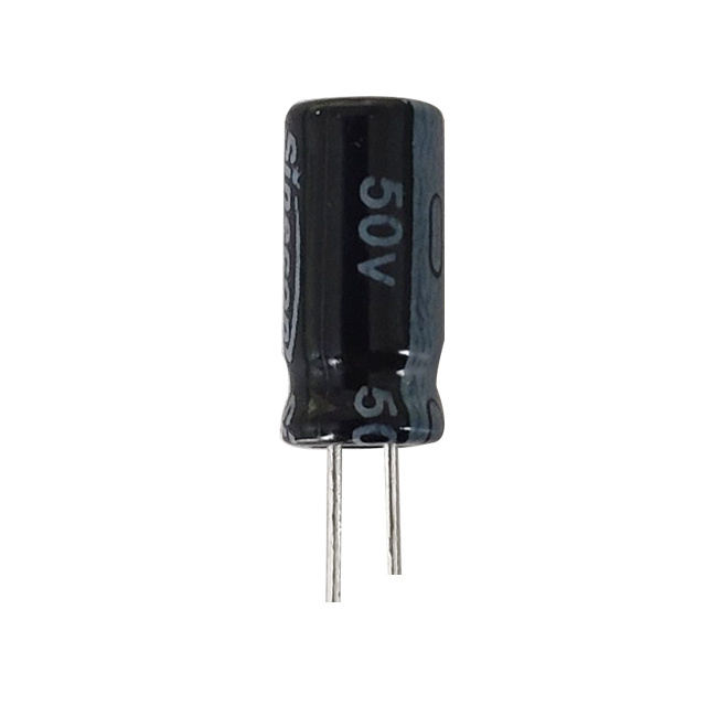
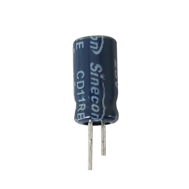
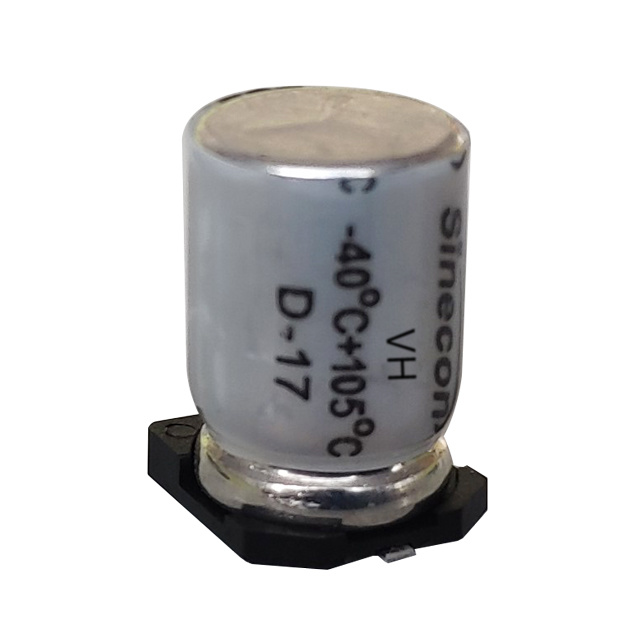
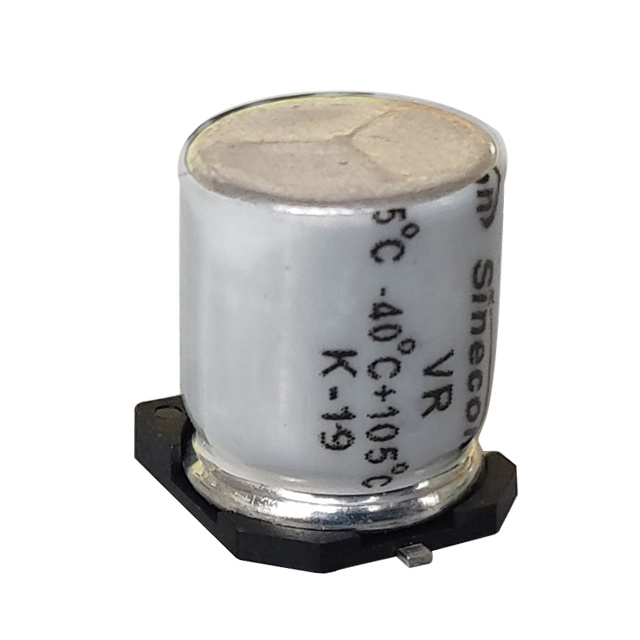
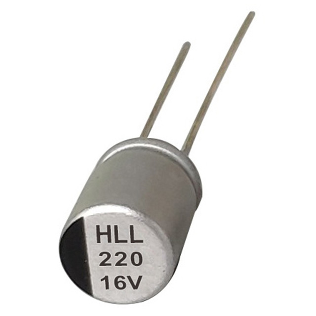
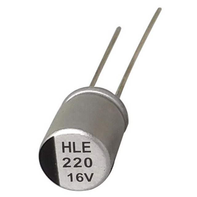
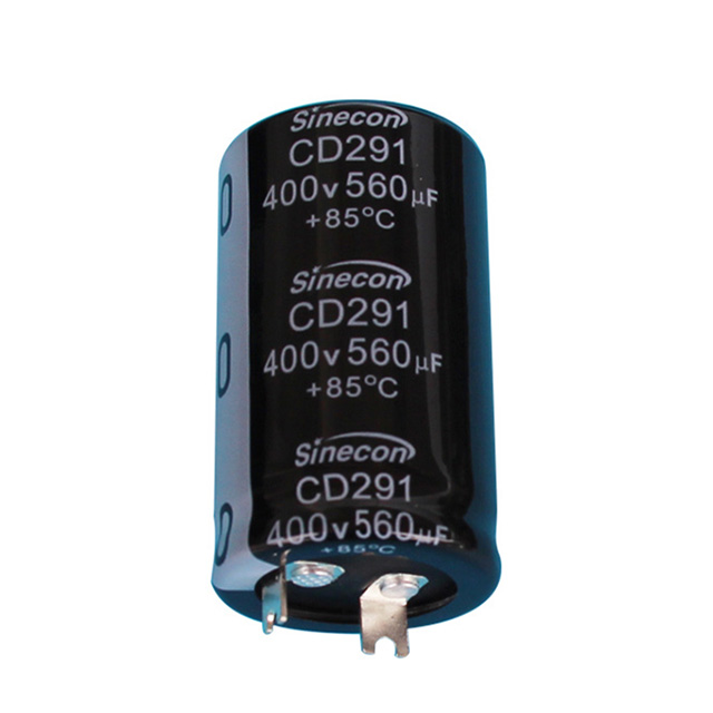
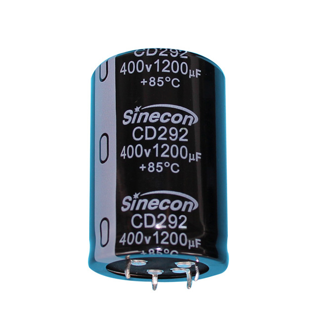
Electrolytic capacitors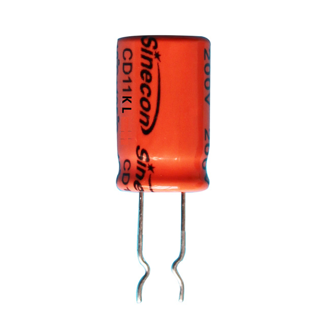
In a typical 12V, 2A linear supply, a 2,200 µF to 4,700 µF capacitor rated at 25V or higher is common to keep ripple voltage under 100 mV. Undersized capacitance leads to excessive ripple, which can cause audible hum in audio equipment or instability in digital logic circuits downstream.
Switching Power Supplies
In switch-mode power supplies (SMPS), electrolytic capacitors are placed both at the input, to absorb the DC bus voltage, and at the output, to filter high-frequency switching noise combined with lower-frequency ripple. Because SMPS designs often operate at switching frequencies from 20 kHz to several hundred kHz, designers select capacitors with low equivalent series resistance (ESR) and adequate ripple current ratings to prevent overheating and premature failure.
Rectifier and DC Bus Circuits
In full-wave and half-wave rectifier stages, electrolytic capacitors sit directly after the diode bridge to convert pulsating DC into usable, near-constant DC voltage. This application is found in everything from battery chargers to uninterruptible power supplies (UPS) and welding equipment.
Larger industrial systems, such as variable frequency drives (VFDs) and motor controllers, rely on a "DC bus" — a group of high-voltage electrolytic capacitors, often rated between 400V and 900V, connected in series or parallel banks. These capacitors store energy from the rectified AC line and supply it to the inverter stage that drives the motor. A single VFD DC bus may use several capacitors rated at 1,000 µF to 3,300 µF each, combined to reach the total capacitance and voltage rating required.
Motor Start and Run Circuits
Single-phase induction motors, such as those found in air conditioners, refrigeration compressors, and pumps, cannot generate a rotating magnetic field on their own. A start capacitor — almost always electrolytic due to the high capacitance needed for a brief, high-current pulse — creates a phase shift in the auxiliary winding to get the motor spinning. Once the motor reaches roughly 75% of its rated speed, a centrifugal switch or relay disconnects the start capacitor from the circuit.
Determining AC Capacitor Size
Choosing the correct ac capacitor size is critical for motor reliability. Start capacitors are typically rated between 88 µF and 400 µF for residential HVAC motors, while run capacitors (which stay in the circuit continuously and are often oil-filled rather than pure electrolytic) range from 3 µF to 70 µF. Installing an undersized capacitor causes the motor to draw excess current and overheat; an oversized one can lead to unstable start torque or capacitor failure. Manufacturers list the correct microfarad rating and voltage rating on the motor's nameplate, and it's important to match both values, not just capacitance.
| Application | Capacitor Type | Typical Range | Voltage Rating |
|---|---|---|---|
| HVAC Compressor Start | Electrolytic | 88–400 µF | 125–330V AC |
| HVAC Fan Motor Run | Oil-Filled Film | 3–15 µF | 370–440V AC |
| Pump Motor Start | Electrolytic | 100–330 µF | 125–250V AC |
Warning
Reversing polarity on a standard electrolytic capacitor, or substituting one in an AC-only circuit without confirming it is non-polarized, can cause rapid overheating and catastrophic failure.
Audio Coupling and Decoupling Circuits
In audio electronics, electrolytic capacitors serve two main roles: coupling and decoupling. A coupling capacitor blocks the DC bias of one amplifier stage while allowing the AC audio signal to pass through to the next stage. A decoupling (or bypass) capacitor sits across the power rails near an amplifier IC to absorb voltage spikes and prevent noise from feeding back into the signal path.
Values in these circuits are usually smaller than in power supplies, ranging from 1 µF to 470 µF, but the quality of the dielectric and the equivalent series resistance directly affect frequency response and distortion. This is why some high-end audio designs replace electrolytic capacitors in the signal path with film capacitors, reserving electrolytics for power supply decoupling where their large capacitance is genuinely needed and their minor tonal coloration is inaudible.
Timing, Filtering, and Energy Storage Circuits
Because electrolytic capacitors offer large capacitance at low cost, they are frequently used in RC (resistor-capacitor) timing circuits where long delay periods are needed — for example, in soft-start circuits, timer relays, or LED flash controllers. They are also used in low-pass filter stages where a large capacitance value is required to filter out low-frequency ripple or noise without needing an impractically large resistor.
Additional common uses include:
- Energy storage buffers in camera flash circuits and defibrillators
- Bulk capacitance in LED driver circuits to reduce flicker
- Snubber circuits to absorb voltage transients across switching devices
- Backup power reservoirs in memory-retention circuits
How to Test an Electrolytic Capacitor
Because electrolytic capacitors degrade over time — particularly under heat and ripple current stress — testing them is a routine part of troubleshooting power supplies, motor circuits, and audio equipment. Knowing how to read a capacitor with multimeter functions can quickly confirm whether a suspect part is still within spec.
Checking Capacitor with Ohm Meter
On an analog multimeter, checking capacitor with ohm meter settings involves discharging the capacitor first, then touching the probes to its leads while observing the resistance needle. A healthy capacitor will show low resistance initially, then climb toward infinity as it charges from the meter's internal battery. If the needle stays at zero (a short) or never moves at all (an open circuit), the capacitor has failed.
How to Check a Capacitor Using Digital Multimeter
Most modern digital multimeters include a dedicated capacitance (µF) mode, making it easier to understand how to check a capacitor using digital multimeter functions directly. The process is straightforward:
- Power down the circuit and discharge the capacitor safely using a resistor across its leads
- Remove the capacitor from the circuit, or at least disconnect one leg, to avoid parallel component interference
- Set the multimeter dial to the capacitance (F) setting
- Connect the probes to the leads, respecting polarity if the meter requires it
- Compare the reading to the value printed on the capacitor body, allowing for its rated tolerance, typically ±20%
Danger
A reading significantly below the rated value, or a display that shows "0" or "OL," generally indicates a dried-out or failed capacitor that should be replaced. Bulging tops, leaking electrolyte, or a burnt smell are visual signs that testing should be done with extra caution.
Selecting the Right Electrolytic Capacitor
Choosing the correct electrolytic capacitor for a given circuit involves more than matching capacitance. Voltage rating should include a safety margin of at least 20% above the maximum expected circuit voltage. Ripple current rating matters most in power supply and motor applications, where excessive heating from insufficient rating shortens component life. Temperature rating (commonly 85°C or 105°C) affects service life significantly — as a general rule, every 10°C reduction in operating temperature roughly doubles the capacitor's expected lifespan.
Info
For circuits carrying AC-like ripple or bidirectional voltage, such as some crossover networks or motor run circuits, a non-polarized (bipolar) electrolytic capacitor is required instead of a standard polarized type.
Summary of Common Applications
Electrolytic capacitors remain the go-to component whenever a circuit needs substantial capacitance in a compact, affordable form. Their primary roles across industries include:
- Smoothing and filtering ripple in linear and switching power supplies
- Storing and delivering energy in rectifier and DC bus circuits
- Providing the starting torque phase shift in single-phase AC motors
- Coupling and decoupling signals in audio amplifier stages
- Enabling long-duration timing circuits and low-frequency filters
Takeaway
Understanding these applications helps in both selecting the right part during design and diagnosing failures during repair. Regular testing with a multimeter's capacitance mode, paired with a visual inspection for bulging or leaking, is the most reliable way to catch a failing electrolytic capacitor before it disrupts an entire circuit.