Introduction to Radial Capacitors
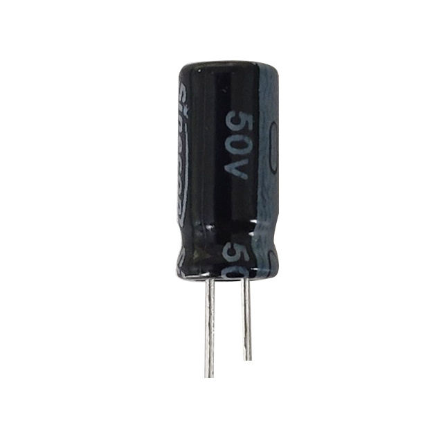
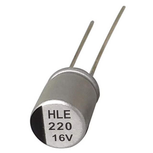
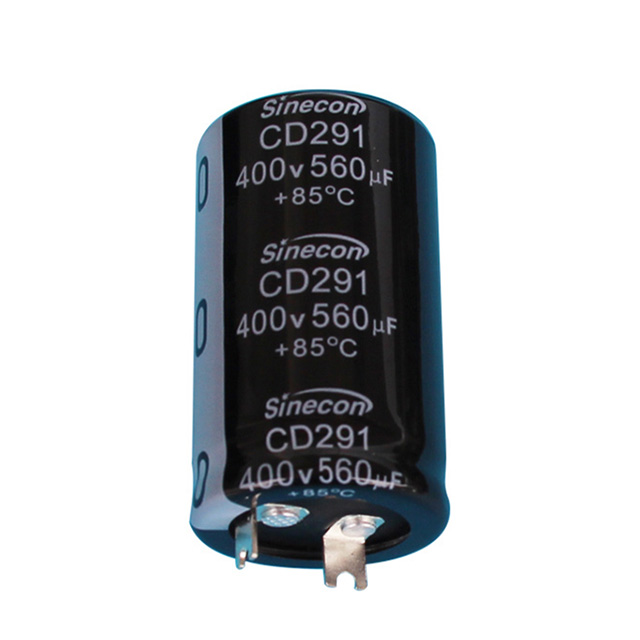
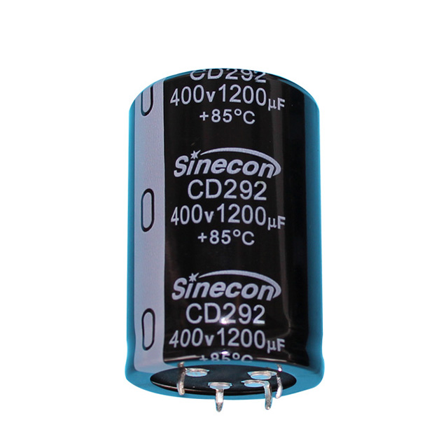
Radial electrolytic capacitors are among the most common electronic components found in modern circuit designs. These cylindrical components with two leads emerging from the same end play a crucial role in power supply filtering, energy storage, and signal coupling applications. Unlike their axial counterparts with leads at opposite ends, radial capacitors offer a more compact footprint that makes them ideal for densely populated printed circuit boards (PCBs).
The term "electrolytic" refers to their construction method which uses an electrolyte to achieve significantly higher capacitance values than other capacitor types. This makes them particularly valuable in applications requiring substantial energy storage or effective ripple current filtering in power supply circuits.
Historical Development
The development of modern electrolytic capacitors began in the early 20th century. The first practical electrolytic capacitor was patented by Samuel Ruben in 1925, which used a tantalum pentoxide dielectric. Aluminum electrolytic capacitors followed soon after, with the first wet electrolytic capacitors appearing in the 1930s. The radial lead configuration became popular in the 1960s as electronic devices began shrinking in size while increasing in complexity.
Fundamental Principles
At their core, electrolytic capacitors operate on the same fundamental principle as all capacitors: energy storage in an electric field between two conducting plates separated by a dielectric material. What makes electrolytic capacitors unique is that one "plate" is actually an electrolyte solution, and the dielectric is an extremely thin oxide layer that forms on the metal anode. This construction allows for much higher capacitance values in a smaller volume compared to other capacitor types.
Construction and Materials
Understanding the internal construction of radial electrolytic capacitors is essential for proper selection and application. These capacitors consist of several key components:
Anode and Cathode
The anode is typically made from aluminum or tantalum foil that has been electrochemically etched to increase its surface area. This etching process creates microscopic pores and valleys that dramatically increase the effective surface area, sometimes by a factor of 100 or more. The cathode is typically an electrolyte-soaked paper or a conductive polymer.
Dielectric Layer
The dielectric is an oxide layer that forms on the anode surface through an electrochemical process called "forming." For aluminum electrolytics, this is aluminum oxide (Al₂O₃) with a thickness of about 1 nanometer per volt of rated voltage. This incredibly thin layer is what enables the high capacitance values.
Electrolyte Composition
The electrolyte serves as the true cathode in wet electrolytic capacitors. Modern electrolytes are complex chemical mixtures optimized for:
- High conductivity
- Low viscosity for good impregnation
- Chemical stability over temperature
- Low vapor pressure to minimize drying
- Compatibility with the oxide layer
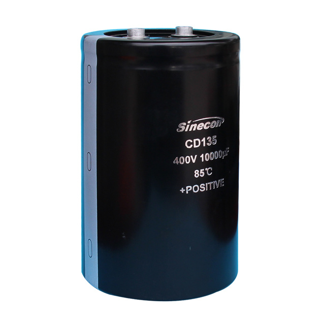
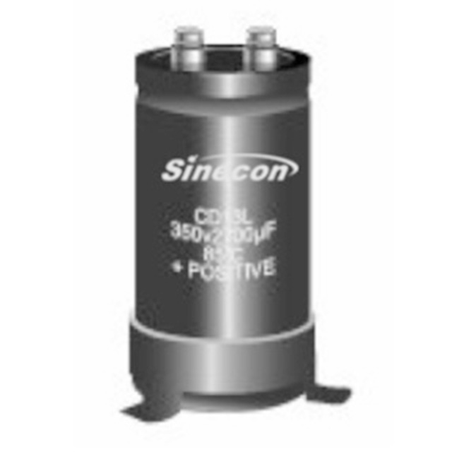
Encapsulation and Sealing
The capacitor element is sealed in an aluminum can with a rubber or polymer seal at the base. The seal must prevent electrolyte leakage while allowing pressure release in case of internal gas generation. Modern capacitors often include safety vents that rupture in a controlled manner if internal pressure becomes excessive.
Key Specifications and Parameters
Understanding capacitor specifications is crucial for proper component selection. Here are the most critical parameters for radial electrolytic capacitors:
| Parameter | Description | Typical Range | Importance |
| Capacitance | Charge storage capacity | 0.1μF to 100,000μF | Determines energy storage and filtering effectiveness |
| Rated Voltage | Maximum continuous DC voltage | 6.3V to 550V | Critical for reliability and safety |
| Ripple Current | Maximum AC current at specified frequency | Milliamps to Amps | Determines power handling capability |
| Equivalent Series Resistance (ESR) | Internal resistance at specified frequency | 5mΩ to 5Ω | Affects heat generation and filtering efficiency |
| Leakage Current | DC current through dielectric | Microamps to milliamps | Important for energy-sensitive applications |
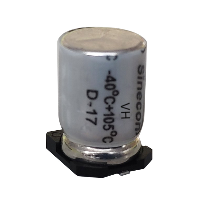
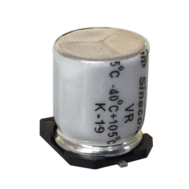
| Temperature Range | Operating temperature limits | -40°C to +105°C (extended to +125°C/150°C) | Determines environmental suitability |
| Lifetime | Expected service life at rated temperature | 1,000 to 20,000 hours | Critical for maintenance planning |
Capacitance Tolerance
Electrolytic capacitors typically have wider tolerances than other capacitor types, usually -20% to +80% for standard parts. This is due to the complex electrochemical processes involved in their manufacture. High-precision electrolytics are available with tighter tolerances (±10% or better) for applications where exact capacitance values are critical.
ESR and Impedance
Equivalent Series Resistance (ESR) is one of the most important parameters in modern capacitor selection, especially for switch-mode power supply applications. ESR represents the sum of all internal resistive losses and causes energy dissipation in the form of heat. Lower ESR values allow capacitors to handle higher ripple currents and operate cooler.
Temperature Effects
Temperature has a significant impact on electrolytic capacitor performance. As temperature decreases:
- Capacitance decreases (can drop 20-50% at -40°C)
- ESR increases substantially (can increase 10x or more at -40°C)
- Leakage current decreases
At high temperatures, the opposite occurs, but chemical reactions accelerate, reducing operating life. The Arrhenius equation predicts that capacitor life halves for every 10°C increase in operating temperature above the rated temperature.
Advantages and Disadvantages
Advantages
- High capacitance-to-volume ratio: Offer the highest capacitance values available in small packages
- Cost-effective: Generally less expensive per microfarad than other capacitor technologies
- Wide voltage range: Available with ratings from a few volts to several hundred volts
- Good self-healing properties: Minor dielectric defects can be repaired during operation
- Ease of use: Simple two-lead configuration with clear polarity markings
- Good frequency response: Suitable for a wide range of applications from DC to moderate frequencies
Disadvantages
- Polarity sensitivity: Must be connected with correct polarity to avoid damage
- Limited shelf life: Electrolyte can dry out over time, especially at high temperatures
- Higher leakage current: Compared to film or ceramic capacitors
- Limited lifetime: Electrolyte evaporation eventually causes failure
- Temperature sensitivity: Performance parameters change significantly with temperature
- ESR limitations: Generally higher ESR than polymer or ceramic capacitors
Applications of Radial Capacitors
Power Supply Filtering
The most common application for radial electrolytic capacitors is in power supply circuits, where they smooth the rectified AC voltage to create a stable DC supply. They absorb voltage fluctuations and provide instantaneous current during peak demands.
Audio Equipment
In audio circuits, electrolytics are used for coupling and decoupling applications. They block DC while allowing AC signals to pass, enabling stage-to-stage coupling without affecting bias voltages.
Motor Start Circuits
Single-phase AC motors often use electrolytic capacitors to create the phase shift needed for starting. These capacitors must handle high surge currents and are specifically designed for motor applications.
DC-DC Converters
Switch-mode power supplies use electrolytics for both input and output filtering. The capacitor's ability to handle high ripple currents makes it ideal for these applications.
Energy Storage
In applications requiring short-term power backup or high pulse currents, electrolytics provide compact energy storage solutions. Examples include camera flash circuits and power conditioning systems.
Signal Coupling
In analog circuits, electrolytics are used to pass AC signals while blocking DC components. Their high capacitance values allow them to work effectively at low frequencies.
Selection Criteria
Choosing the right radial electrolytic capacitor requires careful consideration of several factors:
Voltage Rating
Select a capacitor with a voltage rating at least 20-50% higher than the maximum expected voltage in the circuit. This derating accounts for voltage spikes, transients, and long-term reliability. Operating near or at the rated voltage significantly reduces capacitor life.
Capacitance Value
Determine the required capacitance based on the application:
- For power supply filtering, calculate based on acceptable ripple voltage
- For timing circuits, calculate based on required time constants
- For decoupling, follow manufacturer recommendations for specific ICs
Temperature Considerations
Select capacitors rated for the maximum operating temperature in your application. Remember that internal temperatures can be significantly higher than ambient due to self-heating from ripple current. For high-reliability applications, choose capacitors rated for 105°C rather than 85°C.
Lifetime Requirements
Calculate expected lifetime using the formula:
L2 = L1 × 2(T1-T2)/10 × (VR1/VR2)n
Where T is temperature in °C, VR is working voltage, and n is a voltage acceleration factor (typically 3-7).
Installation and Handling
Proper installation and handling are crucial for reliability:
PCB Layout Considerations
When designing PCBs for radial electrolytics:
- Maintain adequate clearance between capacitors for ventilation
- Keep away from heat sources when possible
- Follow manufacturer recommendations for pad size and spacing
- Ensure sufficient copper area for heat dissipation
Soldering Techniques
Proper soldering is essential to prevent damage:
- Use temperature-controlled soldering irons (max 350°C)
- Limit soldering time to 3-5 seconds per lead
- Avoid excessive mechanical stress on leads
- Never solder by heating the capacitor body
- Follow manufacturer's reflow profiles for SMD versions
Storage and Shelf Life
Electrolytic capacitors degrade during storage:
- Store in cool, dry environments (below 30°C)
- Rotate stock using FIFO (First In, First Out) system
- Reform capacitors that have been stored for extended periods (>1 year)
- Avoid storing near chemicals or solvents
Failure Modes and Troubleshooting
Understanding common failure modes helps with troubleshooting and prevention:
Common Failure Mechanisms
Electrolytic capacitors fail through several mechanisms:
- Electrolyte evaporation: The most common failure mode, especially at high temperatures
- Venting: Pressure build-up causes safety vent to open
- ESR increase: Due to electrolyte loss or degradation
- Capacitance loss: Gradual decrease in storage capacity
- Short circuits: Dielectric breakdown causing catastrophic failure
- Lead corrosion: Particularly in high-humidity environments
Preventive Maintenance
To maximize capacitor life:
- Operate below maximum temperature ratings
- Ensure adequate airflow around components
- Periodically test ESR and capacitance in critical applications
- Implement voltage derating practices
- Monitor for physical signs of distress (bulging tops, electrolyte leakage)
Future Trends
Radial electrolytic capacitor technology continues to evolve:
Conductive Polymer Electrolytes
Solid polymer capacitors offer lower ESR, longer life, and better temperature stability than traditional liquid electrolytics. These are increasingly replacing standard electrolytics in demanding applications.
Hybrid Technologies
Combining liquid electrolyte with polymer materials creates capacitors with the best characteristics of both technologies - high capacitance density with low ESR and extended lifetime.
Miniaturization
Ongoing research focuses on increasing capacitance density while reducing package sizes. This includes improved etching techniques, higher-purity materials, and enhanced electrolyte formulations.
Extended Temperature Ranges
New electrolyte formulations are enabling capacitors that operate reliably at temperatures up to 150°C, meeting the demands of automotive, aerospace, and industrial applications.
Conclusion
Radial electrolytic capacitors remain essential components in modern electronics despite the emergence of alternative technologies. Their unique combination of high capacitance values, cost-effectiveness, and availability in a wide range of specifications ensures their continued relevance in power supply design, audio equipment, and countless other applications.
When selecting radial electrolytics, designers must carefully consider voltage ratings, ripple current specifications, ESR, temperature requirements, and expected lifetime. Proper installation, handling, and maintenance practices significantly impact reliability and performance. As technology advances, new formulations and constructions continue to address previous limitations, ensuring that these components will remain vital in electronic designs for the foreseeable future.