 English
 русский
 Tiếng Việt
 Español

A field guide to reading the earliest and clearest warning sign an electrolytic capacitor gives before it takes the rest of the board down with it.
The Direct Answer: What a Bulging Capacitor Top Means
A bulging or swollen electrolytic capacitor top means the component has failed or is actively failing, and it should be replaced immediately. The dome-shaped deformation on top of the capacitor is caused by internal gas pressure building up inside the aluminum can, usually as a result of the electrolyte fluid boiling, drying out, or reacting chemically due to heat, age, overvoltage, or ripple current stress. When this pressure exceeds what the case can safely hold, the metal top physically deforms outward, and in more advanced cases it splits open along pre-scored vent grooves to release gas and vapor. A bulged top is one of the most reliable visual signs of capacitor failure, and unlike some electrical faults, it does not require any tools to detect — just a careful look at the board.
That said, a bulging top is a late-stage symptom. By the time the case has visibly deformed, the capacitor has usually already lost a significant portion of its rated capacitance and its ability to filter voltage properly. This means that even if a device still powers on, a bulging capacitor is not something to monitor or wait out — it is something to replace before it causes cascading damage to other components on the board.
Why Electrolytic Capacitors Bulge in the First Place
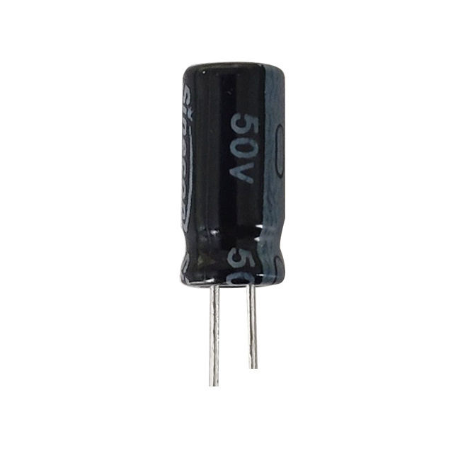
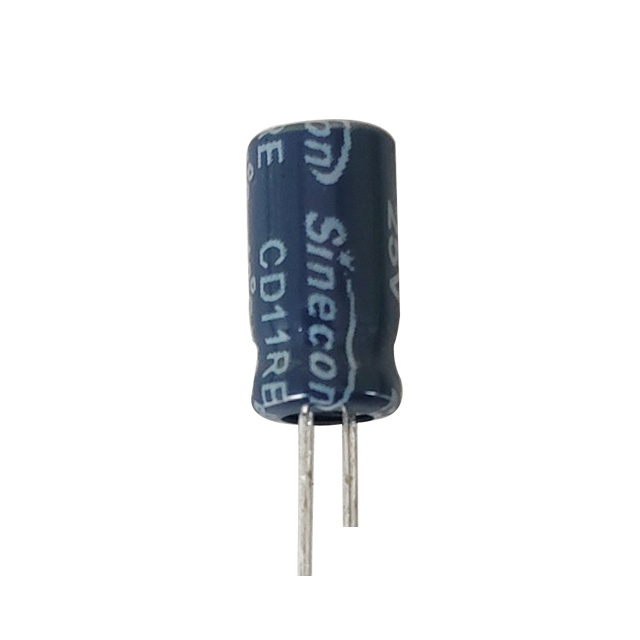
To understand why the top swells, it helps to understand the basic construction. An electrolytic capacitor consists of two aluminum foil electrodes separated by an oxide layer and soaked in a liquid or gel electrolyte, all rolled up and sealed inside a cylindrical aluminum can. That liquid electrolyte is the key to the capacitor's high capacitance in a small package, but it is also the component's biggest weakness, because liquids are sensitive to heat, chemical breakdown, and evaporation over time.
electrolytic capacitor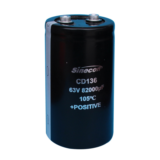
What Causes a Capacitor to Fail
Understanding what causes a capacitor to fail makes it much easier to predict which components on a board are at risk before they even start bulging. The most common contributing factors include:
- Prolonged exposure to heat, especially from nearby power transistors, voltage regulators, or CPUs running above the capacitor's rated temperature
- Ripple current that exceeds the capacitor's rated tolerance, generating internal heat with every switching cycle
- Applied voltage that exceeds the rated working voltage, even briefly during power surges
- Natural aging, since electrolyte gradually evaporates through the rubber seal even under normal operating conditions
- Manufacturing defects, including electrolyte formulations that break down prematurely or seals that were not properly cured
- Reverse polarity installation, which causes rapid internal gas generation within seconds to minutes
Any of these factors can raise the internal temperature of the electrolyte to the point where it begins to vaporize. Since the capacitor is a sealed can, that vapor has nowhere to go except to push outward on the weakest point of the structure, which is almost always the flat top.
Reverse polarity installation causes rapid internal gas generation within seconds to minutes — this is the fastest path to a ruptured case, not a gradual one.
The Purpose of the Vent Grooves on Top
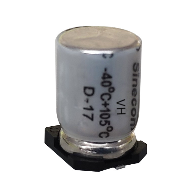
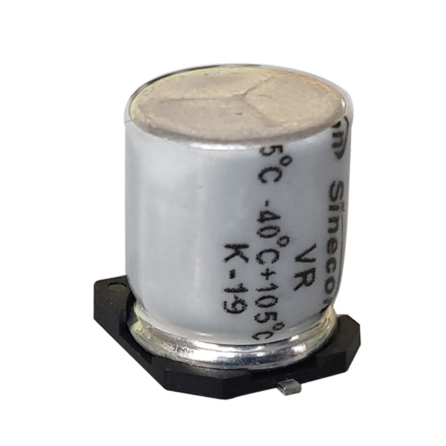
Most electrolytic capacitors have a top marked with an X, K, or Y-shaped groove pressed into the metal. This is not decorative — it is a deliberate pressure relief feature. The groove is thinner than the surrounding metal, so when internal pressure builds beyond a safe threshold, the groove is designed to split open before the entire can ruptures uncontrollably or, in rare severe cases, before the capacitor explodes.
Once the groove has visibly separated and dried or crusted electrolyte residue is present around the vent, the capacitor has already released internal pressure and its capacitance has almost certainly dropped well outside its rated tolerance, commonly by 20% or more from the original rated value.
In many field failure cases, capacitance loss exceeds 50% by the time visible venting has occurred.
Stages of Visual Deformation
| Stage | Visual Appearance | Recommended Action |
|---|---|---|
| Early | Top is completely flat, no dome visible | Monitor during routine inspection |
| Mild bulging | Slight dome, grooves not yet separated | Test capacitance and plan replacement soon |
| Moderate bulging | Pronounced dome, grooves partially opened | Replace before continued use |
| Severe venting | Groove split open, crusted residue visible | Replace immediately, inspect surrounding components |
Bulging Is Not Always the First Sign of Trouble
It is worth stressing that a capacitor can be electrically bad well before its case shows any visible deformation. Capacitance can drift downward, and equivalent series resistance (ESR) can climb significantly, all while the top remains perfectly flat. This is especially common with capacitors that fail due to gradual electrolyte drying rather than sudden overpressure. In these cases, relying on a visual inspection alone will miss the problem entirely.
A visual check should always be treated as a first-pass screening step, not a final diagnosis. If a device shows instability, overheating, or intermittent shutdowns but none of the capacitors appear visibly bulged, the next step is to check capacitor using digital multimeter to confirm whether the values are still within an acceptable range.
How to Check Capacitor Using Digital Multimeter
A basic digital multimeter with a capacitance testing function can confirm what a visual inspection only suggests. Follow this general sequence:
- Power down the device completely and unplug it from any power source
- Discharge the capacitor safely using a resistor across its terminals, since even a small capacitor can retain a shock-worthy charge
- Desolder at least one leg of the capacitor to isolate it from the rest of the circuit, since in-circuit readings are frequently distorted by parallel components
- Set the multimeter dial to the capacitance setting, usually marked with a capacitor symbol or the letter F for farads
- Connect the probes to the capacitor terminals, matching polarity if the meter requires it
- Compare the displayed reading against the rated capacitance value printed on the capacitor's body
Most electrolytic capacitors are rated with a tolerance of plus or minus 20%. A reading that falls outside this range — for example, a capacitor rated at 1000 microfarads reading below 800 microfarads — indicates the component has degraded and should be replaced regardless of whether the case shows visible bulging.
Checking ESR for a More Complete Picture
A standard multimeter's capacitance mode does not measure equivalent series resistance, which is often the earliest indicator of internal degradation. A dedicated ESR meter or a multimeter with an ESR function can catch capacitors that still read close to their rated capacitance but have already developed excessive internal resistance, a condition that causes overheating and reduced filtering performance even before the case begins to deform.
Where Bulging Capacitors Are Most Commonly Found
Bulging is not random — it clusters in predictable locations on a circuit board. Capacitors positioned near voltage regulators, switching power supplies, motor drivers, or any component that generates continuous heat are exposed to higher thermal stress and therefore fail at a noticeably higher rate than capacitors placed in cooler areas of the same board. Power supply input and output filtering stages are particularly high-risk zones because they combine both elevated temperature and continuous ripple current.
When inspecting a board, it is worth paying closer attention to any capacitor sitting directly next to a heat sink, transformer, or switching regulator, since these locations statistically account for a disproportionate share of visible bulging cases compared to capacitors elsewhere on the same assembly.
What to Do After Spotting a Bulging Capacitor
Once a bulging capacitor is confirmed, the safest course of action is straightforward replacement rather than continued operation. Running a device with a known-bad capacitor risks secondary damage, since a failing filter capacitor allows more ripple voltage to pass downstream, which can stress other sensitive components such as integrated circuits and semiconductors that were never designed to tolerate that level of electrical noise.
- Match the replacement capacitor's capacitance, voltage rating, and physical size to the original component
- Choose a replacement with an equal or higher temperature rating if the original was located in a high-heat area
- Inspect the surrounding solder pads and traces for any heat discoloration or corrosion caused by leaked electrolyte
- Check neighboring capacitors on the same board, since capacitors from the same production batch and exposed to the same conditions often fail around the same time
Matching capacitance, voltage rating, physical size, and temperature tolerance to the original component — then checking neighboring capacitors from the same batch — is the surest way to close out a repair without a repeat failure.
Final Takeaway
A bulging or swollen top on an electrolytic capacitor is a clear signal of internal pressure buildup caused by heat, age, electrical stress, or a manufacturing defect, and it reliably indicates that the capacitor's performance has already degraded. While this visual sign is easy to catch during a routine inspection, it should not be treated as the only diagnostic tool. Pairing a visual check with an electrical test to check capacitor using digital multimeter gives a far more complete and accurate picture of a capacitor's true condition, catching failures long before the case ever begins to deform.