 English
 русский
 Tiếng Việt
 Español

Imagine that you are selecting the bulk capacitor for a 48 V industrial power supply. The steady-state rail measures 52 V, and load-step transients ring up to 58 V. A 63 V capacitor seems close enough, a 75 V part looks safer, and both are far below the capacitor's actual breakdown voltage. The design question, then, is not whether the part can survive at 58 V. It almost certainly can. The real question is how much long-term reliability you are willing to trade for that apparent headroom.
Breakdown voltage in an electrolytic capacitor is the voltage at which the aluminum oxide dielectric stops behaving as an insulator and starts to conduct. It is a physical limit set by the thickness of the oxide layer grown on the anode foil. Every voltage rating printed on the capacitor, including rated voltage, surge voltage, and transient voltage, exists to keep the dielectric safely below that limit. This article explains how that limit is established, what happens when it is crossed, and how to select a voltage rating with the right margin.
What Is Breakdown Voltage in an Electrolytic Capacitor?
Aluminum electrolytic capacitors store charge in a thin layer of aluminum oxide (Al2O3) formed electrochemically on the surface of etched anode foil. During the forming process, the oxide grows to a thickness proportional to the applied forming voltage, at a rate of roughly 1.2 to 1.5 nanometers per volt. A capacitor with a 100 V rated voltage therefore carries an oxide layer in the range of 120 to 150 nm, and that thickness is the main factor that determines the dielectric's breakdown voltage.
When a forward DC voltage is applied, the oxide layer must hold off the electric field between the anode and the electrolyte. If the voltage rises far enough, the field exceeds the dielectric strength of the oxide. Electrons begin to tunnel through microscopic defects, leakage current climbs sharply, and localized heating follows. In a wet, liquid-electrolyte capacitor, the heat can decompose the electrolyte and generate gas. In a solid polymer capacitor, the same overvoltage more often produces a hard short circuit.
Because the oxide thickness is fixed at the end of manufacturing, the breakdown voltage of a finished capacitor is a physical property, not a value that shifts with temperature or ripple. The published ratings are chosen with a deliberate margin below it.
Rated Voltage, Surge Voltage, and Breakdown Voltage: How They Relate
The rated voltage is the maximum continuous DC voltage the capacitor is designed to handle at its rated temperature while meeting all life, ripple, and leakage specifications. The surge voltage is a non-repetitive overvoltage that the capacitor can tolerate for a short period and is defined individually for each series. Both are placed well below the dielectric breakdown limit.
| Parameter | Meaning | Relationship to breakdown voltage |
|---|---|---|
| Rated voltage (DC) | Maximum continuous DC voltage at rated temperature for which the capacitor meets its lifetime and ripple specifications | Typically 60 to 80 percent of the breakdown voltage |
| Surge voltage | Maximum non-repetitive overvoltage the capacitor can survive for a short, defined duration | Between rated voltage and breakdown voltage |
| Transient voltage | Short-duration voltage spike the capacitor may see during switching, load steps, or system events | Above rated voltage but still below breakdown voltage |
| Breakdown voltage | Voltage at which the aluminum oxide dielectric loses its insulating property and conducts current | The physical limit itself |
For a typical aluminum electrolytic capacitor, the rated voltage lands between 60 and 80 percent of the breakdown voltage. A 63 V rated part, for instance, may not break down until roughly 85 to 100 V. That internal margin is what allows the capacitor to survive surge testing, voltage spikes, and brief overvoltage events without immediate failure. It should not be treated as usable rating.
What Happens When the Breakdown Voltage Is Exceeded?
Operating above the rated voltage but below the breakdown limit is not instantly fatal, but it is harmful. Leakage current rises, the oxide layer experiences increased field stress, and the electrolyte is consumed faster. Repeated excursions close to the breakdown point gradually reduce capacitance and increase ESR, which in a liquid-electrolyte part translates into measurable life loss.
Crossing the breakdown voltage is a different event. The weakest spot in the oxide carries an increasing current, and the localized temperature drives further breakdown. In wet aluminum electrolytic capacitors, a small defect may self-heal, because the heat regenerates oxide at the damaged site. With higher energy available, gas generation opens the pressure vent and the capacitor is destroyed. Solid polymer capacitors have almost no self-healing ability in this mode, and their failure is typically an internal short circuit.
Reverse polarity must be treated as a separate failure condition. The key oxide layer exists only on the anode, so a reverse voltage attacks the thin oxide on the cathode foil. Even a low reverse voltage can destroy that layer quickly. Capacitors exposed to reverse bias during power-up or shutdown should be specified as bipolar or protected by the circuit design.
How to Select a Voltage Rating with the Right Margin
The practical starting point is the worst-case voltage the capacitor will see, not the nominal bus voltage. Add the peak of any AC ripple or transient ringing to the maximum DC level, then apply a derating factor. A common rule for aluminum electrolytic capacitors is to keep the maximum applied voltage at or below 80 percent of the rated voltage. For severe transient environments, many designers target 65 to 70 percent.
Return to the 48 V bus example. With a 52 V steady-state maximum and a 58 V worst-case transient, the 80 percent rule demands a rated voltage of at least 72.5 V. The nearest standard ratings are 75 V and 80 V, so a 75 V capacitor becomes the engineering choice, while a 63 V part clears the transient by only 8 percent. The cost of the safer choice is physical size, because a higher voltage rating implies a thicker oxide and, for the same capacitance, a larger can.
- Measure or simulate the worst-case peak voltage at the capacitor terminals, including DC tolerance, ripple, load steps, and startup overshoot.
- Multiply that peak by the derating factor used in your reliability target, usually 1.2 or higher.
- Select the nearest standard voltage rating above the result.
- Confirm that the chosen part's surge voltage rating also clears your worst transient peak.
Radial parts for board-level DC buses
Radial lead capacitors are common in board-level DC buses, and we have examined how the voltage rating of radial electrolytic capacitors impacts circuit reliability in a separate article. In the radial format, the CD11H ultra-high-voltage long-life radial capacitor series is designed for sustained DC stress in medium- and high-voltage positions.
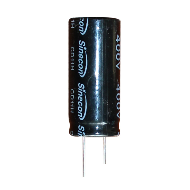 CD11H Ultra-High Voltage Long-Life Radial Aluminum Electrolytic Capacitor SuppliNantong Xingchen Electron Co., Ltd. is China Wholesale CD11H Ultra-High Voltage Long-Life Radial Aluminum Electrolytic Capacitor Supplier...View Product →
Snap-in parts for compact high-power stages
At higher power levels, snap-in capacitors take over. When a rectifier or inverter stage needs high capacitance in a compact, board-mounted package, a part such as the CD297 ultra-high-voltage low-leakage long-life snap-in capacitor series offers a high rated voltage while keeping leakage current low.
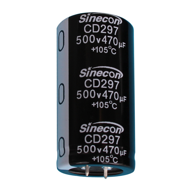 CD297 Ultra-High Voltage, Low Leakage, Long-Life Snap-In Aluminum Electrolytic CNantong Xingchen Electron Co., Ltd. is China Wholesale CD297 Ultra-High Voltage, Low Leakage, Long-Life Snap-In Aluminum Electrolytic Cap...View Product →
What This Means for Your Design
Breakdown voltage is a useful concept for understanding why capacitors fail, but it is not a design parameter. Design with the rated voltage, respect the surge rating, and keep a derating margin that matches the transient severity of your circuit. A capacitor operated at 60 to 80 percent of its rated voltage will meet its life claim; one operated at the edge of its rating may not. Choosing a higher voltage class, and accepting the associated case size, is usually a small price for predictable performance.
For industrial converters that run at very high rail voltages and significant ripple current, screw-terminal construction is often the practical format. The CD136 high-voltage high-temperature screw-terminal capacitor series, for example, is built for continuous operation at elevated ambient temperatures, which helps preserve the manufacturer's specified voltage and lifetime limits.
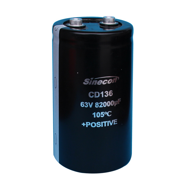 CD136 High Voltage And High Temperature Resistant Terminal Aluminum ElectrolyticNantong Xingchen Electron Co., Ltd. is China Wholesale CD136 High Voltage And High Temperature Resistant Terminal Aluminum Electrolytic C...View Product →
Before you finalize a part number, measure or simulate the worst-case peak voltage at the capacitor terminals, including ripple, load steps, and startup overshoot. If that peak comes within 20 percent of the rated voltage, move to the next voltage class. Your lifetime estimate and your reliability reviews will both be healthier for it.