 English
 русский
 Tiếng Việt
 Español

Aluminum Electrolytic Capacitors: The Engineer’s Field Guide
A practical look at the parameters that decide real-world performance, written for engineers and procurement teams who need to move from a datasheet to a confident decision.
During a design review for a 3 kW industrial drive, the most heated discussion was not about the control loop or the switching device. It was about a single 470 µF electrolytic capacitor: which series, which temperature rating, and whether the ripple current calculated at 20 kHz was really within its capability. That scene is typical in power electronics, because few passive components carry as much responsibility as the aluminum electrolytic capacitor.
Conclusion first: if you focus only on capacitance and rated voltage, the rest of the system can pay for it with poor thermal margin, shorter field life, or an unstable control loop. This guide walks through the five most useful performance parameters — ESR, ripple current, lifetime, voltage derating, and package style — and connects each one to real applications.
Why Aluminum Electrolytic Capacitors Still Matter
An aluminum electrolytic capacitor stores charge in the oxide layer formed on etched aluminum foil. The etched foil creates a very large effective surface area, the oxide layer acts as the dielectric, and the electrolyte completes the cathode connection. That construction is why electrolytic capacitors can deliver high capacitance in a compact cylindrical package.
Compared with ceramic capacitors, they store far more energy at high voltage. Compared with film capacitors, they are smaller and cheaper for the same capacitance. The trade-offs are real: they are polarized, they lose capacitance at low temperature, and they age as electrolyte evaporates. These limits are not reasons to avoid them. They are reasons to specify them carefully.
Without electrolytic capacitors, DC-link stages in solar inverters, charging piles, variable frequency drives, UPS systems, and switched-mode power supplies would need much larger film capacitors or complex active balancing circuits. That is why this component remains the default choice, not a legacy one.
Five Parameters That Decide Real-World Performance
When a capacitor fails in the field, the root cause can almost always be traced to one of five parameters: ESR, ripple current, lifetime, voltage derating, or the wrong package style. The rest of this section looks at each one from a practical angle.
ESR: The Silent Source of Heat
Equivalent series resistance represents the internal losses of the capacitor. These losses behave like a real resistor, and the heat they generate equals the square of the ripple current multiplied by the ESR. A 3 A rms ripple current through a 100 mΩ ESR produces close to 0.9 W of heat inside a component that may weigh only a few grams. In a compact design, that is enough to raise the core temperature noticeably and shorten lifetime. A low-ESR series should therefore be your first choice in high-frequency power circuits, and the ESR value at the actual operating temperature — not only the 25 °C datasheet number — is what matters.
For a deeper look at what causes ESR and how it affects circuit behavior, see this technical note on ESR in aluminum electrolytic capacitors.
Ripple Current and Core Temperature
Rated ripple current is the rms current a capacitor can handle without exceeding a specified internal temperature rise. Manufacturers usually state it at a reference frequency, often 100 Hz or 120 Hz, and at a maximum ambient temperature such as 85 °C or 105 °C. A capacitor used in a 20 kHz converter may handle a very different current than the 120 Hz rating suggests, because ESR changes with frequency. If your output stage operates at 20 kHz, verify the frequency-correction curve in the datasheet or ask the manufacturer for the ripple current derating factor. Ignoring this detail is one of the most common causes of overheating and premature field failure.
Engineering rule of thumb: every 10 °C reduction in core temperature roughly doubles the useful life of a liquid aluminum electrolytic capacitor. Every 10 °C increase roughly halves it.
Lifetime: Not Just an Hour Count
Lifetime curves are based on the hot-spot temperature inside the winding, not on the case temperature measured with a probe on the can. A capacitor mounted next to a hot inductor or power resistor can run much hotter at its core than its shell suggests. For a reliable design, use the core temperature for the lifetime estimate and keep margin above the application’s worst-case ambient condition.
Voltage Derating and Polarity
Rated voltage is the maximum DC voltage the capacitor can withstand continuously, and surge voltage is the maximum it can tolerate for a short period, usually about 1.1 times the rated value. For long-term reliability, operate at 80–90 % of rated voltage; derating reduces dielectric stress and extends life, especially at high temperature. Liquid aluminum electrolytic capacitors are polarized. Reverse voltage of even one or two volts can damage the oxide layer, generate gas, and trigger the pressure relief vent. If the circuit may see polarity reversal, choose a bipolar type or add protection. Bipolar series such as the CD71 are designed for audio coupling and S-correction circuits where the terminal polarity is not fixed.
Package Styles Define the Application Boundary
The package style is not just a mechanical preference; it determines how much current the capacitor can carry, how heat escapes, and how easily the part fits into your production line. Five styles cover most power electronics applications.
Radial Lead and Snap-In: Workhorses of Low and Medium Power
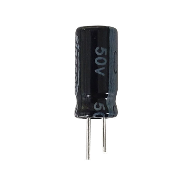
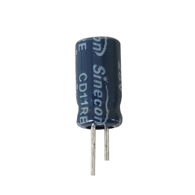
Radial lead capacitors are the classic through-hole components found in power adapters, LED drivers, and appliance control boards. They are inexpensive, widely available, and easy to design around, although they require auto-insertion or hand assembly. Snap-in capacitors occupy the next power tier: two or four pins lock the component to the board and handle higher ripple current for UPS units, welding machines, and medium-power drives. Within the radial family, middle- and high-voltage series are developed for the DC-link bus of inverters and charging modules, where high voltage, low leakage, and long life matter more than size alone.
Screw Terminal: Built for High Ripple and Thermal Stress
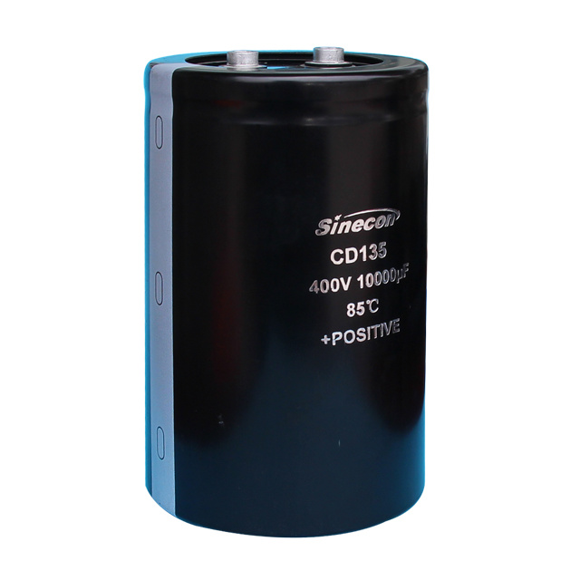
For multi-kilowatt converters, screw terminal capacitors provide a low-resistance connection path and a large cylindrical body that helps conduct heat away from the core. The threaded terminal reduces connection resistance, and the larger body allows much higher ripple ratings. These parts are common in high-power charging piles, large UPS phases, servo drives, and medium-voltage wind converters.
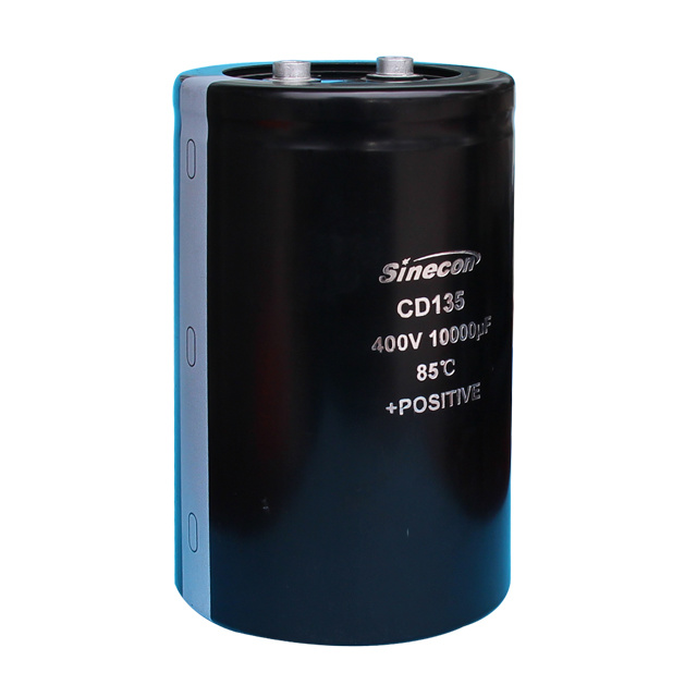 CD135 Screw Terminal Aluminum Electrolytic Capacitor for High Ripple PowerThis screw-terminal capacitor suits high-power converters and industrial stages where low connection resistance and high ripple handling are essential, making it a practical choice for demanding multi-kilowatt applications.View Product →
Solid Polymer: Low ESR Without Lifetime Trade-Offs
Solid polymer aluminum capacitors replace the liquid electrolyte with a conductive polymer. ESR drops to a few milliohms, low-temperature behavior improves, and lifetime no longer depends on electrolyte evaporation. The main limitations are a lower maximum voltage, usually below 200 V, and a slightly higher leakage current than good liquid types. For the output stage of a 48 V DC-DC converter or a low-voltage DC link, a polymer is often the right answer.
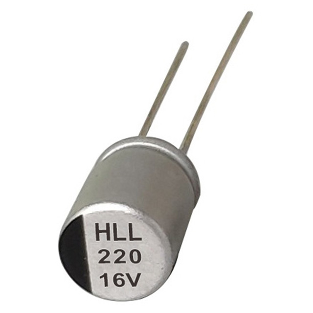
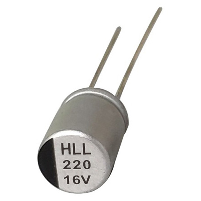 HLL Radial Polymer Capacitor with Low ESR and High Ripple CapabilityAs a solid polymer type, this component provides very low ESR and stable high-frequency performance, fitting well in 48 V DC-DC output stages or low-voltage DC links where liquid electrolyte limitations matter.View Product →
| Package style | Typical ESR | Ripple handling | Best suited for |
|---|---|---|---|
| Radial lead | Medium to high | Low to medium | Adaptors, LED drivers, small power supplies |
| Snap-in | Medium | Medium to high | UPS, welding equipment, medium drives |
| Screw terminal | Low to medium | Very high | Charging piles, large inverters, heavy drives |
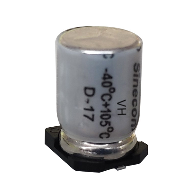
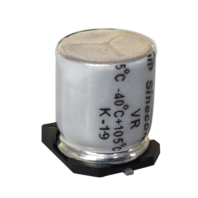
| SMD / chip | Medium | Low to medium | Compact consumer electronics, automotive modules |
| Solid polymer | Very low | Medium to high | DC-DC outputs, fast charging, low-voltage high-frequency circuits |
Application-First Selection Thinking
Once the package style is clear, the application conditions define which parameter deserves the most attention. The list below shows how common power electronics applications translate into priorities.
- Solar and wind inverter DC link: high voltage, high ripple, warm enclosure; choose long-life radial or screw-terminal types with adequate voltage derating.
- EV charging piles: continuous high ripple and outdoor temperature swings; screw-terminal series with high ripple ratings are usually the right fit.
- Communication power supplies and UPS: reliability matters more than price; a long-life series with low ESR and documented field data reduces maintenance.
- Audio equipment: bipolar or nonpolar radial types prevent DC bias from distorting sound; audio-specific series also offer lower loss.
- Fast chargers and LED lighting: board space is tight and switching frequency is high; small radial or surface-mount types with low ESR are preferred.
In renewable-energy inverters, the DC-link capacitor operates close to the maximum DC voltage for long periods. An ultra-high-voltage radial series such as the CD11H handles the elevated bus voltage while offering a long service life at high ambient temperatures. That kind of component-level choice shows up in thermal images years later: the correct voltage class, the right lifetime, and a package that actually fits the assembly process.
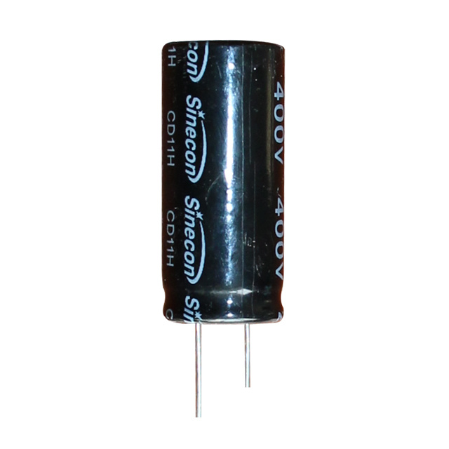 CD11H Ultra-High Voltage Long-Life Radial Aluminum Electrolytic CapacitorWith voltage ratings up to 500 V and extended life at elevated temperatures, this radial capacitor is well suited for DC-link roles in renewable inverters and other high-voltage, long-duration operation.View Product →
What to Look for in an Electrolytic Capacitor Manufacturer
Component selection does not end with the datasheet. Production consistency determines whether three thousand capacitors behave like three thousand identical parts, or like a statistical lottery. A mature capacitor maker should be able to show full-process control: material traceability, in-line aging, automatic sorting, and final testing of capacitance, tan δ, leakage current, and ESR.
When sourcing from a manufacturer, ask for leakage current distribution and high-temperature load-life test results, not just typical datasheet values. Batch-to-batch stability matters especially for SMT production, where a single bad batch can stop an entire assembly line.
A Quick Selection Checklist
- Define the core operating temperature: ambient temperature plus self-heating from ripple current, not simply the PCB temperature.
- Calculate the rms ripple current at the actual switching frequency and compare it with the rated value after frequency correction.
- Check ESR at the lowest expected operating temperature, especially for liquid electrolyte types.
- Select a rated voltage at least 10–20 % above the maximum bus voltage, including transients.
- Choose the package style based on ripple, thermal path, board area, and assembly process.
- Estimate lifetime using the core temperature and the 10 °C rule; add margin for end-of-life drift.
- Verify that capacitance tolerance meets the circuit requirement, especially in timing or filter circuits.
- Request batch traceability and complete inspection reports from the supplier.
Aluminum electrolytic capacitors are often treated as a commodity, but the field failure rate of cheap or mis-specified parts tells a different story. If you focus on the five parameters above and verify the supplier’s consistency, you can build power electronics that stays reliable for years. At the design stage, an electrolytic capacitor deserves the same attention as the switching device or the control IC.
For engineers looking for a production partner with deep experience in radial, snap-in, screw terminal, and polymer capacitor families, Nantong Xingchen Electron has been manufacturing aluminum electrolytic capacitors since 1985 and offers a broad range of series for exactly these applications.