 English
 русский
 Tiếng Việt
 Español

Capacitors and Power Factor: Why the Classic Fix Still Wins
A plant's power factor drifts below the utility's contract threshold, and the monthly bill climbs even though production never changed. The most economical correction is rarely a larger transformer — it is a bank of capacitors sized to the load. Capacitors supply the leading reactive current that cancels the lagging current drawn by motors and transformers, and they do it passively, reliably, and at a fraction of the cost of re-engineering the supply.
What Power Factor Actually Tells You
Power factor is the ratio of working power to total power drawn — real power in kilowatts divided by apparent power in kilovolt-amperes. At a power factor of 1.0, every ampere on the bill does useful work. At 0.7, roughly thirty percent of the current is circulating through the system without producing torque, heat, or light.
The split becomes clearer when you separate the three quantities:
- Real power (kW) — the portion that turns motors, heats elements, and drives control circuits.
- Reactive power (kVAr) — the portion that sustains the magnetic fields in motor windings, transformer cores, and chokes.
- Apparent power (kVA) — the vector sum of the two, and the value the utility must transform, switch, and carry.
That last point drives the economics. Cables, transformers, and breakers are all rated in kVA. When the power factor drops, the same kilowatts demand more kilovolt-amperes, which raises current, raises I2R losses, and forces heavier equipment for the same useful load. Utilities therefore apply a penalty below their contract threshold — commonly in the 0.85 to 0.95 band — and the penalty grows as the power factor falls.
Where the Lag Comes From
The culprits are inductive loads. Induction motors, transformers, welding machines, ballasts, and filter chokes draw current that lags the voltage because their magnetic fields take time to build and collapse. The phase angle between the current and voltage waveforms is φ, and cos φ is the power factor. The deeper the lag, the lower the cosine, and the larger the circulating current.
A motor's power factor is not a fixed number. At full load, most induction motors sit between 0.80 and 0.88 while running economically. Derate the same motor to half load, and the power factor can fall below 0.60 because the magnetizing current stays roughly constant while the useful current shrinks. Oversized motors installed "for safety" are one of the most common causes of a chronically low plant power factor.
Why Capacitors Are the Cure
Capacitors behave in the opposite sense. In a clean capacitor, current leads voltage by nearly 90°, so a capacitor connected in parallel with an inductive load can cancel the lagging reactive current locally — before it reaches the meter. That is why correction banks are installed at the service entrance, at distribution panels, or directly across large motors: the reactive power is exchanged at the point where the utility measures it.
A capacitor does not generate reactive power. It stores energy for half a cycle and returns it in the next, so the inductive load and the capacitor exchange reactive power with each other while the supply sees only the remaining active component.
Why capacitors rather than inductors? An inductor shifts current in the same direction as the load and makes the lag deeper. Capacitors are passive, modular, and low-maintenance: bank sections can be switched in steps to track a changing load, and a properly applied bank has no moving parts. The only real discipline is not to overshoot, because a leading power factor brings its own penalties and overvoltage risks.
Sizing a Correction Bank
Once you have an existing power factor and a target, the calculation is compact:
Qc = P × (tan φ1 − tan φ2), where Qc is the required capacitance in kVAr, P is the real load in kW, and φ1 and φ2 are the phase angles before and after correction. The table below gives the working multiplier for a 0.95 target, which is the value most industrial tariffs treat as good practice.
| Existing Power Factor | Required kVAr per kW |
|---|---|
| 0.60 | 1.005 |
| 0.70 | 0.692 |
| 0.80 | 0.421 |
| 0.85 | 0.291 |
| 0.90 | 0.156 |
| 0.95 | 0.000 |
Example: a plant draws 400 kW at 0.70 power factor and wants 0.95. The required capacitance is 400 × 0.692 ≈ 277 kVAr. That result is a starting point, not the final word. Partial loading and existing harmonics change the practical size, so the final bank is best defined from a short measurement campaign rather than a single nameplate check. Over-correcting to exactly 1.0 is the most common sizing error; the operating window you actually want is roughly 0.95 to 0.98.
Choosing the Right Capacitor Hardware
On the AC side, traditional correction banks use film capacitors rated for continuous mains duty. An aluminum electrolytic capacitor is polarized and must never sit directly on an AC line. In modern power electronics, however, power factor correction is mostly active: the converter shapes the input current to follow the voltage, and an aluminum electrolytic capacitor in the DC link absorbs the ripple and holds the bus voltage stable. That is where product selection matters, and where the supplier's structure becomes important.
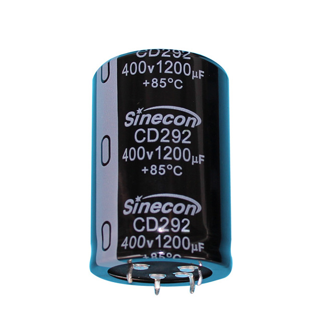
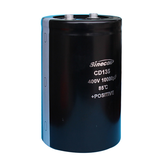 CD135 High-Ripple Screw Terminal Aluminum Electrolytic CapacitorFor DC-link applications in PFC supplies, this screw-terminal capacitor handles high ripple current and provides a robust thermal path via its terminal, suiting industrial drives and inverters.View Product →
The DC-link capacitor in a power-factor-corrected supply sees two demanding conditions: a large ripple component at twice the mains frequency, plus the high-frequency current from the switching stage. Both produce heat, and heat sets the life of the component. For industrial drives, welding equipment, and large inverters, a screw-terminal capacitor with a strong ripple-current rating is the usual answer, and the terminal form creates a robust thermal path to a bus bar or heat sink. The interface behavior is detailed in this guide to screw-terminal capacitor selection.
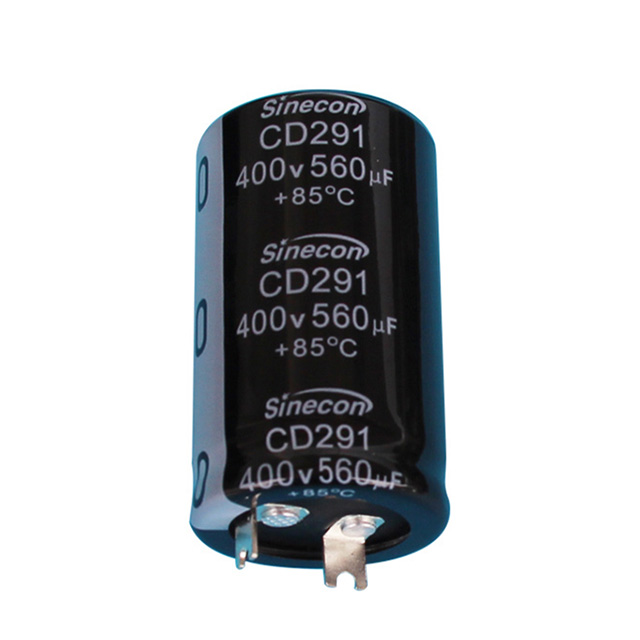
For medium-power PFC stages — on-board chargers, networking supplies, machine drives — snap-in terminals are the practical choice because they mount directly on the PCB, handle substantial ripple, and keep long life in a confined enclosure.
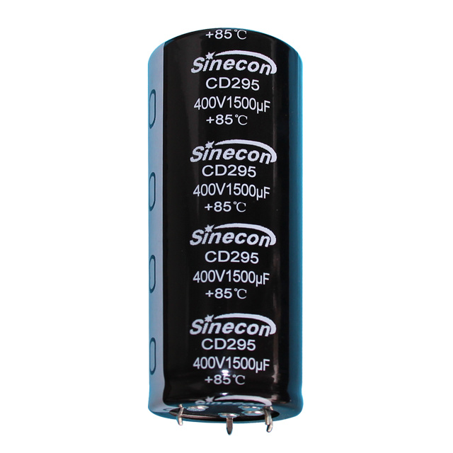 CD295 Durable High-Ripple Snap-In Aluminum Electrolytic CapacitorDesigned for medium-power PFC stages, this snap-in capacitor offers up to 5000 hours of life, high ripple tolerance, and a wide voltage range, making it reliable for chargers and machine drives.View Product →
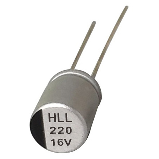
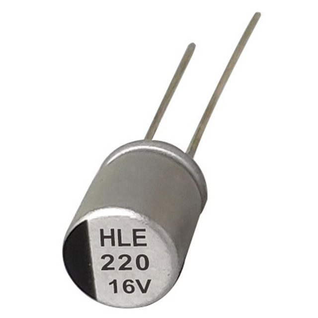
At the compact end of the spectrum, radial polymer capacitors exchange some capacitance for an order-of-magnitude lower ESR. In PFC stages with high ripple current and tight board space, that lower ESR translates into less internal heating and simpler thermal layouts.
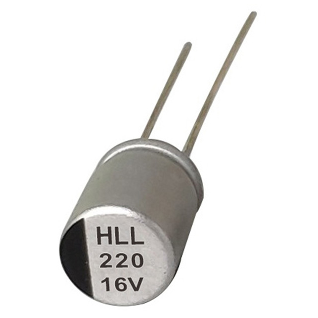 HLL Low-ESR Radial Polymer Aluminum Electrolytic CapacitorWith low ESR and high ripple capability in a compact radial polymer package, this capacitor reduces heat generation, making it ideal for power supplies and voltage regulation circuits.View Product →
Whatever the chemistry, the selection routine stays the same:
- Confirm the steady-state bus voltage and choose a rated voltage at least 20% higher.
- Measure the ripple current at the operating frequency; the capacitor must exceed it, not merely meet it.
- Estimate life from the ripple-current and ambient-temperature curves rather than the nominal hour rating.
- Match the terminal style to the assembly: screw-terminal for bus-bar construction, snap-in for PCB mounting, polymer radial for compact low-ESR stages.
Common Mistakes That Shorten Capacitor Life
Capacitors fail early when the application does not match the chemistry. Most field problems trace back to four avoidable situations.
The Bottom Line
Capacitors correct power factor because they supply the leading reactive current that cancels the lagging current drawn by inductive loads. The correction is passive, modular, and quick to pay back, provided the bank is sized from a measured power factor and kept inside the 0.95 to 0.98 window. Where correction is active — inside switching supplies, inverters, and chargers — the aluminum electrolytic capacitor in the DC link is the component that absorbs ripple and sustains the bus, so its voltage margin, ripple rating, and thermal life deserve the same attention as the kVAr calculation itself.
That is the practical connection between a capacitor and power factor: the passive bank sharpens the grid side, and the electrolytic capacitor stabilizes the converter side. If you are defining a capacitor specification for a PFC design, the full range of aluminum electrolytic capacitors is a solid starting point for the discussion on ripple current, terminal style, and expected service life.