 English
 русский
 Tiếng Việt
 Español

The arithmetic takes ten seconds. Choosing the voltage to put into it, and trusting the answer at minus forty degrees, takes considerably longer.
A 450 V snap-in capacitor on a 400 V DC link looks generously rated until a cold-start test catches 60 V of switching overshoot riding on the ripple. The part that passed every spreadsheet check suddenly becomes the reason the board goes back for a layout change. What catches that mistake is not a more elaborate formula, but a clearer reading of the simplest one: i = C · dv/dt.
So here is the short answer before the detail. That single derivative relationship tells you how fast voltage moves for a given current, and every other expression engineers use — charge, energy, RC rise and fall, ripple — is a rearrangement of it. Rated voltage, ESR, temperature, and lifetime do not change the arithmetic, but they decide whether the arithmetic still describes the part in your hand.
The sections below cover the forms worth memorizing, the assumptions that quietly break them, and the checks that stop a passing calculation from becoming a failing product.
The Capacitor Voltage Equations Worth Keeping at Hand
Six forms cover almost every practical case. They are not alternatives to each other; each answers a different question, and confusing them is the most common source of wrong answers in power-design work.
| Equation | What it tells you | Where it is used |
|---|---|---|
| i = C · dv/dt | Current required to move the voltage at a chosen rate | Snubber design, slew-rate limits, dv/dt stress |
| ΔV = I · Δt / C | Voltage change produced by a current pulse of known duration | Ripple estimation, pulse loads, charge injection |
| Q = C · V | Charge stored at a given voltage | Charge balance, reset circuits, sampling networks |
| E = ½ · C · V² | Energy available for a discharge event | Hold-up time, bleeder resistors, safety analysis |
| Vc(t) = Vs (1 - e^(-t/RC)) | Voltage while charging toward a supply through resistance | Soft start, power-up delay, inrush limiting |
| Vc(t) = V0 · e^(-t/RC) | Voltage while discharging from a known starting point | Hold-up time, safe discharge timing |
Notice what is missing from that table: temperature, frequency, and time. These equations describe an ideal element, and the difference between the ideal answer and the measured one is where most of the engineering effort actually lives.
Working the Derivative Form by Hand
Two quick calculations make the numbers concrete. A 1000 µF capacitor carrying 5 A of net current changes voltage at dv/dt = i / C = 5 / 0.001, which is 5000 V per second, or 5 V per millisecond. At that rate, a bus capacitor with a poorly matched load can cross its rated voltage inside a single switching event.
Run the same relationship the other way. A 470 µF capacitor absorbing 2 A of ripple current for 8 µs, roughly the on-time of a mid-frequency stage, moves by ΔV = I · Δt / C = (2 × 0.000008) / 0.00047, or about 34 mV. Keep that figure in mind, because it is only the capacitive half of the ripple you will see on a scope.
The voltage across a capacitor is a record of the current that has flowed into it. When the voltage is wrong, the current history is where the answer is hiding.
The equation is polarity-blind. An aluminum electrolytic capacitor is not. Reverse voltage above roughly one volt damages the oxide layer, so a design in which the voltage genuinely swings both ways needs a bipolar part rather than a rearranged formula.
RC Charging and Discharging Without the Shortcuts
The RC forms look like a separate topic, but they are the derivative relationship after one integration against a constant source. With time constant τ = R × C, the shape of the curve is fixed: a capacitor charging through a resistor reaches 63.2 percent of the supply after one time constant, and a discharging capacitor falls to 36.8 percent of its starting voltage in the same interval.
The rest of the curve is worth knowing without reaching for a calculator:
- 1τ: 63.2 percent charged, 36.8 percent remaining on discharge
- 2τ: 86.5 percent charged, 13.5 percent remaining
- 3τ: 95.0 percent charged, 5.0 percent remaining
- 4τ: 98.2 percent charged, 1.8 percent remaining
- 5τ: 99.3 percent charged, 0.7 percent remaining
Treat five time constants as "effectively settled" rather than "settled." Leakage current keeps pushing a real capacitor slightly past that point, and dielectric absorption means a part that has been shorted for a minute can recover a measurable fraction of its voltage once the short is removed. For safety-related discharge paths, that recovery is exactly why a bleeder resistor sized only from E = ½CV² deserves bench verification.
Ripple Voltage: Where the Ideal Equation Underestimates
Conclusion first: on a real electrolytic capacitor, the voltage you measure is always larger than the ideal capacitive term, and the gap widens as temperature falls. Two mechanisms explain nearly all of it — equivalent series resistance and dielectric loss.
The resistive contribution is easy to estimate: V = I_ripple × ESR. A part with 0.15 Ω of ESR carrying 1.2 A of ripple adds about 180 mV on top of the capacitive term, before any temperature correction. In stages switching at tens of kilohertz, that resistive term usually dominates, which is why a capacitance increase that looks generous on paper can move the measured ripple very little.
ESR is not a constant. A standard aluminum electrolytic that measures 0.2 Ω at 20 °C can measure several times that at minus 40 °C, because electrolyte conductivity collapses in the cold. Ripple designs that pass comfortably at room temperature routinely fail their first cold-start test.
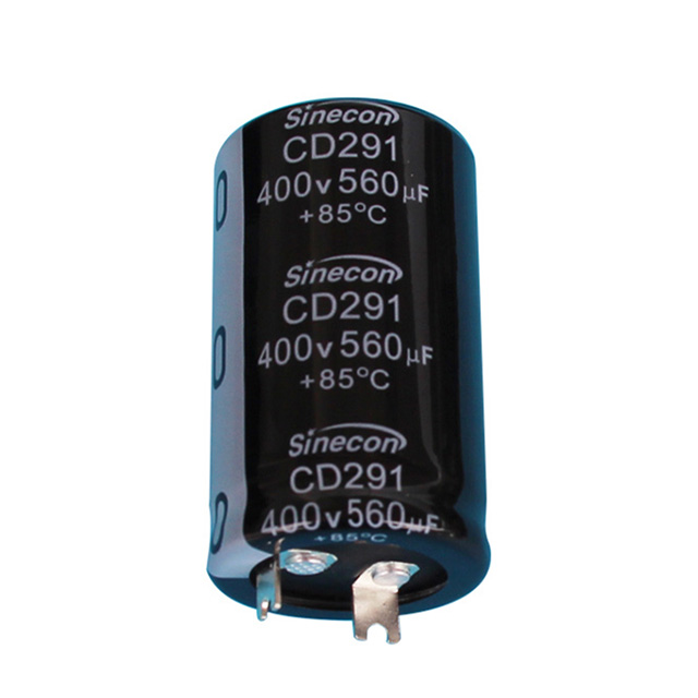
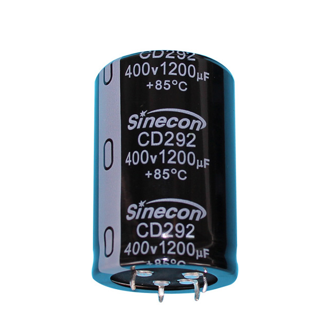
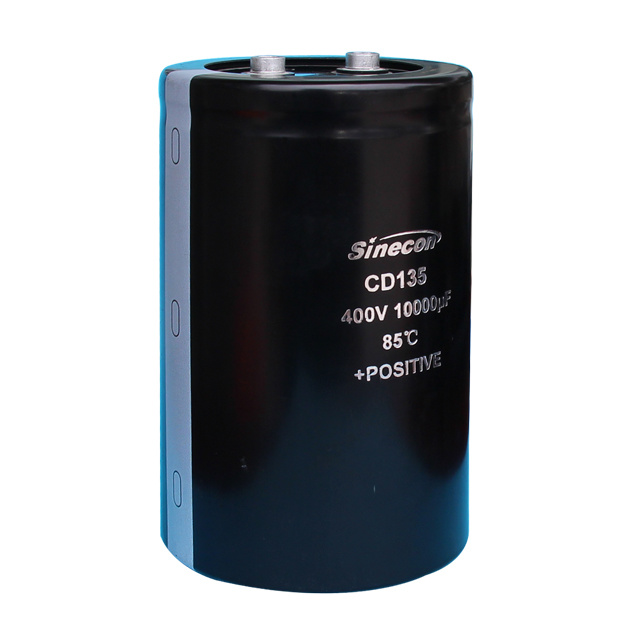
For bulk DC-link positions, high-ripple snap-in series exist precisely to trade capacitance per unit volume against ESR and ripple current rating. The CD293 family is a standard high-ripple snap-in option in that class, built for the kind of continuous ripple a heatsink-free DC link has to absorb.
Rated Voltage, Headroom, and Surge Conditions
Choose the rated voltage from the worst-case peak, never from the nominal rail. The sequence is short but often skipped: take the nominal bus voltage, add the peak ripple, add the switching overshoot measured at the capacitor terminals rather than at the supply, then add a margin for line transients.
In industrial DC links, a 20 to 30 percent gap between worst-case peak and rated voltage is a reasonable working rule. A 400 V bus with 30 V of peak-to-peak ripple and 40 V of overshoot peaks near 460 V, so a 500 V or 550 V part is the honest answer. A 450 V part only works if the overshoot measurement was optimistic.
Surge ratings are a separate specification from continuous ratings. Most datasheets permit a short-duration surge at roughly 1.15 times rated voltage at 25 °C, through a specified series resistance and for a limited time. That allowance is not permission to run at 1.15 times the rating continuously, and it narrows as ambient temperature rises. Where the terminals see fast transients rather than steady ripple, the behavior of screw-terminal electrolytic capacitors under transient voltage is worth reading before the rating is frozen.
Derating also buys service life. Running a part at 80 percent of its rated voltage lowers the electric field across the oxide layer, which slows the electrochemical aging that gradually raises ESR and lowers capacitance.
Temperature, ESR, and Lifetime: What the Equation Cannot See
The capacitor voltage equation has no temperature term, and temperature is where most field failures originate.
Lifetime follows an Arrhenius-style rule of thumb that is accurate enough for planning: every 10 °C reduction in core temperature roughly doubles expected life. A part rated for 2000 hours at 105 °C running with a 65 °C core is looking at about sixteen times that figure, or roughly 32,000 hours. The important word is core — ripple current heats the core above ambient, so an ambient-temperature calculation flatters the result.
Apply the ten-degree rule to core temperature, not ambient. Subtract the ripple-induced temperature rise using the datasheet curve first, because the doubling factor is sensitive to a 10 °C error in either direction.
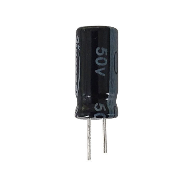
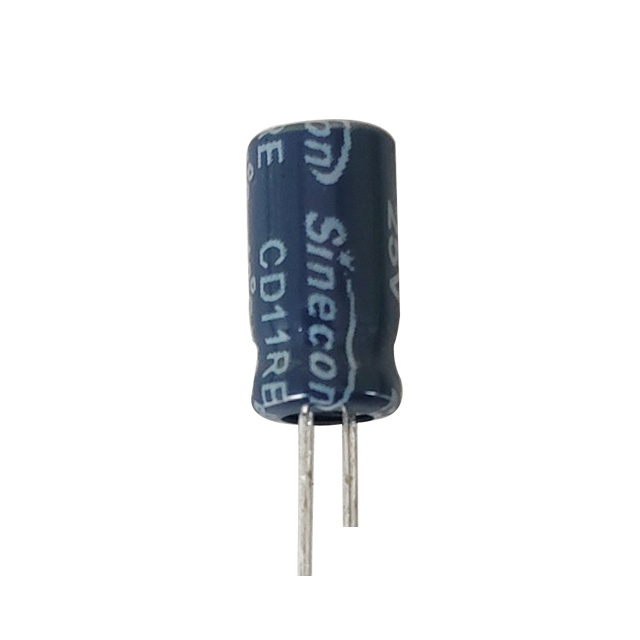
Cold performance is the mirror image of the same problem. Electrolyte conductivity falls with temperature, ESR rises, and the resistive ripple term grows with it. Low-temperature-startable radial series such as CD11GE are specified for exactly that condition, where a part selected only on 20 °C data would show ripple voltage well above the room-temperature calculation.
A Selection Checklist That Keeps the Arithmetic Honest
Run these seven steps in order. Each one can eliminate a candidate before the next adds detail.
- Calculate the worst-case peak voltage at the capacitor terminals, including ripple, overshoot, and line transients.
- Select a rated voltage with 20 to 30 percent headroom above that peak, then confirm the surge rating separately.
- Work out the required capacitance from the ripple budget and from any dv/dt requirement the circuit imposes.
- Check the ripple current rating against actual RMS ripple, applying the datasheet frequency correction factors.
- Verify ESR at the lowest operating temperature, not at 20 °C.
- Estimate core temperature and expected life with ripple heating included.
- Confirm the mechanical fit: case diameter, lead spacing or terminal pitch, height clearance, and mounting orientation.
Step five is the one most often skipped, and step two is the one most often done from habit. Together they account for a large share of the returns that come back with a "capacitor failed" label attached.
Once the numbers are fixed, the shortlist usually narrows to two or three series. Comparing snap-in aluminum electrolytic capacitor options at the same voltage and case size makes the ripple current and lifetime differences visible faster than any single datasheet.
Where the Equation Ends and the Part Begins
The capacitor voltage equation is a two-line idea that survives every level of design work: current moves charge, charge moves voltage, and the rate depends on capacitance. Everything else — rating, derating, ESR, temperature, lifetime — is about whether that idea still describes the component after ten thousand hours in a cabinet that reaches 70 °C in summer.
Use the equation to size, then use specified and measured data to verify. A design that carries both is one where the calculated voltage and the oscilloscope trace agree, in the lab and in the cold, years after the prototype.