 English
 русский
 Tiếng Việt
 Español

Reliability Engineering · Aluminum Electrolytic Capacitors
How to Prevent Capacitor Failure: Causes, Design Tips & Prevention Guide
Capacitor failures rarely arrive without warning. Heat, voltage stress, ripple current, and aging follow predictable patterns — and every one of them can be managed before the failure happens.
The swollen can, the lifted vent, the faint burnt smell — every engineer who has opened a returned power supply knows the signature of a failed aluminum electrolytic capacitor. It is tempting to call it random component failure, exchange the part, and move on. But the failure was rarely random. It was the product of stresses that began at the design stage and compounded month after month, until the component could no longer continue.
Here is the fact that changes how you approach the problem: aluminum electrolytic capacitors have a finite, predictable life. They fail not because they are bad, but because they are worn out — or because the conditions around them exceeded their design limits. Once you accept that, prevention becomes engineering.
Why Aluminum Electrolytic Capacitors Fail
Capacitor failure is not one mechanism. In aluminum electrolytic capacitors, six distinct mechanisms dominate field returns:
- Electrolyte dry-out. The liquid electrolyte evaporates through the rubber seal, especially under heat. Capacitance drops, ESR climbs, and the capacitor eventually opens.
- Dielectric breakdown. Overvoltage or transients puncture the thin oxide layer, causing leakage, short circuit, or vent rupture.
- ESR rise. As the electrolyte degrades, resistance increases, producing more heat under ripple current — and heat accelerates further degradation.
- Capacitance drift. Capacitance falls gradually, weakening filtering and degrading circuit performance.
- Short circuit. Dielectric puncture, contamination, or mechanical damage can create an internal short.
- Mechanical damage. Board flex, vibration, and lead strain fracture internal connections or the seal before electrical life is reached.
Of these, electrolyte dry-out and ESR rise account for most premature failures in power electronics. The chemistry that gives aluminum electrolytic capacitors their high capacitance per volume is the same chemistry that limits their life: every operating hour consumes part of the electrolyte, and as it degrades, the aging process affects both capacitance and ESR in ways that quietly destabilize the surrounding circuit.
Heat Is the Dominant Stressor
Of all the variables an engineer controls, temperature has the largest impact on capacitor life. A practical rule of thumb condenses the Arrhenius behavior of electrolytic aging: for every 10°C rise in core temperature, expected life roughly halves. A capacitor rated for 10,000 hours at 105°C survives about 5,000 hours at 115°C — and about 20,000 hours at 95°C.
What the 10°C rule means in practice: the ambient temperature on the datasheet is not what matters. The core temperature — ambient plus self-heating from ripple current — drives aging. If the core runs 15°C above ambient, the life calculation changes dramatically.
Ripple current is the hidden heating source. Every milliamp of AC current flowing through the capacitor’s ESR dissipates power inside the can, and at high ripple levels the internal temperature can run 10–20°C above ambient. Placement and airflow decide whether that heat is carried away or accumulates.
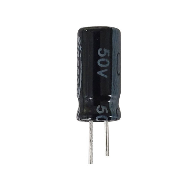
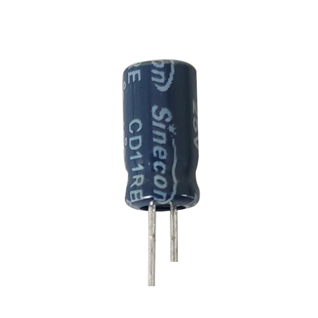
Layout is the first line of defense. Keep capacitors away from transformers, power resistors, and heatsinks, and keep airflow paths clear. When ambient conditions are marginal, choose a higher-temperature-rated series. For sustained heat, the CD11HE high-temperature-resistant radial series preserves stability and low resistance beyond what a general-purpose part can deliver — a sound choice in power stages, lighting, and industrial control boards.
Finally, derate ripple current relative to the datasheet limit at maximum rated temperature. The quoted rating assumes a specific frequency and a hot environment; in a warm enclosure, exceeding it pushes the core temperature beyond the safe window.
Voltage Stress and Transient Protection
Voltage is the second controllable stressor. The dielectric oxide layer inside an electrolytic capacitor is anodized to a specific breakdown strength. Apply more voltage than the oxide can hold — even for a few microseconds — and the layer punctures, leakage climbs, and the capacitor may short or vent.
The industry-standard countermeasure is derating. Keep steady-state DC voltage at or below 80% of rated voltage; for high-reliability applications, 60–70% provides even more margin. That headroom absorbs the transients that occur during start-up, load steps, and mains disturbances.
No margin, no protection. A capacitor running continuously at its rated voltage has zero safety margin. Even a modest surge during a load step can exceed the dielectric limit. Always specify the worst-case voltage — including tolerance and start-up overshoot — and select the next rating above it.
Audit transient sources as well: inductive loads, motor starting, and lightning-induced surges. In harsh conditions, choose capacitors with explicit surge resistance or add protection devices upstream — one of the least expensive reliability improvements a design can carry.
Ripple Current, ESR, and the Hidden Heating Loop
Ripple current is the engine of internal heating. Every amp of AC current flowing through the capacitor’s ESR produces heat, and the relationship is not linear: P = I² × ESR. A capacitor carrying 2 A of ripple with 50 mΩ of ESR dissipates 0.2 W inside a small can — and quadrupling the current quadruples the power. That self-heating shortens life even when ambient temperature looks harmless.
The aging loop is self-reinforcing: heat accelerates electrolyte loss, electrolyte loss raises ESR, and higher ESR generates more heat under the same ripple. Once the loop starts, a part that looked healthy at 10,000 hours can collapse within a few thousand more.
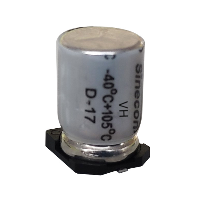
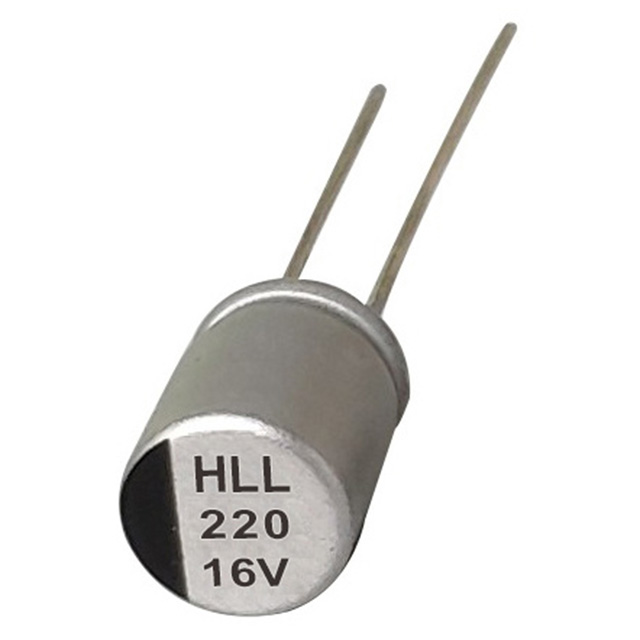
The most direct fix is a capacitor with inherently low ESR. In high-ripple circuits, the HLL radial polymer series combines high ripple capability with low ESR, keeping internal temperature under control while maintaining capacitance stability across frequency. Polymer construction also eliminates the liquid electrolyte that drives dry-out — a key reason these parts appear in high-frequency converters and switched-mode supplies.
Two datasheet cautions. The ripple rating is often quoted at 120 Hz or 100 kHz and at maximum rated temperature; a different waveform or warmer environment demands derating. Also check ESR at the operating frequency, since ESR falls with frequency and a low-frequency figure can mislead.
Failure Modes at a Glance
A clear map of failure modes speeds up design review and field diagnosis:
| Failure Mode | Root Cause | Prevention |
|---|---|---|
| Electrolyte dry-out | High core temperature, normal aging | Stay below rated temperature; use long-life series |
| Dielectric breakdown | Overvoltage, transient surges | Derate voltage; add transient protection |
| ESR rise and self-heating | High ripple current, electrolyte degradation | Use low-ESR series; verify ripple derating |
| Capacitance drift | Normal aging at elevated temperature | Budget for aging in the design; qualify for full lifetime |
| Short circuit | Dielectric puncture, contamination, mechanical stress | Overvoltage protection; controlled assembly and handling |
| Mechanical damage | Board flex, vibration, lead strain | Proper mounting, adhesive or clamp, strain relief |
Selection, Mounting, and Handling: Prevention as a Habit
Match the series to the operating profile
Capacitor series are engineered around different trade-offs. A general-purpose part may deliver attractive capacitance per dollar, but if the product runs for years inside a warm enclosure, the life rating determines whether it outlives the warranty. Long-life series use reinforced seals, lower leakage, and a chemistry that slows electrolyte loss. The CD11FL ultra-long-life medium- and high-voltage radial series, for example, is built for continuous duty in frequency converters, PV inverters, and communication power supplies — where a failure means a costly service visit rather than a part exchange.
Mount to protect the internal connections
Mechanical stress is a quiet killer. When the PCB flexes during assembly, handling, or in-field vibration, stress concentrates at the internal welds between the element and the terminal leads. After thousands of micro-flexures, the connection fractures.
- Align lead spacing precisely with the PCB footprint; never bend leads to force them into place.
- For radial capacitors, secure the body to the board with an adhesive bead or clamp, keeping stress off the internal welds.
- In vibrating equipment, prefer formats with stronger terminations, such as snap-in or screw-terminal types, and add strain relief on connectors.
- Avoid mounting the capacitor on the most flexible region of the board.
Handle and store before assembly
An electrolytic capacitor can lose part of its life before it is soldered. Long-term storage at high humidity or high temperature degrades the seal, raises leakage current, and shortens service life. The general practices for handling and storing aluminum electrolytic capacitors are well documented: keep parts in original sealed packaging, store below 40°C, avoid condensation, and voltage-condition — reform — capacitors that have exceeded shelf life.
Safety note: an aluminum electrolytic capacitor can hold a dangerous charge long after power is off. Always discharge large-format capacitors through a suitable resistor and verify zero voltage before handling. A venting capacitor may also eject hot electrolyte — another reason to design for correct vent orientation and enclosure protection.
An Alternative Worth Considering: Solid Polymer Capacitors
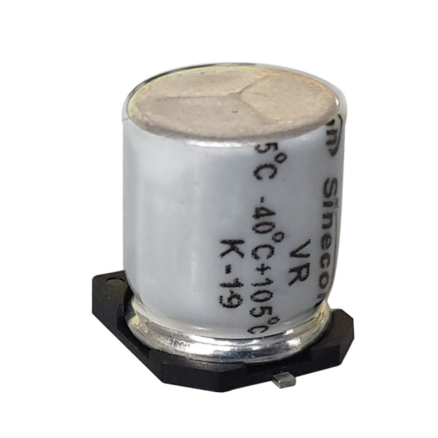
When thermal and ripple demands exceed what liquid-electrolyte types can reliably deliver, solid polymer aluminum electrolytic capacitors offer a different failure profile. The liquid electrolyte is replaced with a conductive polymer that does not evaporate, removing the largest aging mechanism of conventional electrolytics.
Polymer capacitors show a flatter ESR curve across temperature and frequency, higher ripple capability, and a more predictable life in hot environments. The trade-offs: lower rated voltage, higher cost, and a failure signature that is typically short rather than open.
When polymer makes sense: high-frequency switching converters, compact power modules, and any design with a long warranty, a warm enclosure, or heavy ripple demand. If a field failure costs more than the price difference of a polymer part, the polymer is the cheaper component over the product’s lifetime.
Prevention Is a Design Decision
Capacitor failure is not an act of nature. It is the predictable result of temperature, voltage, ripple current, mechanical stress, and the inherent aging of a component whose life is finite by design. Every one of those factors is controllable — at the drawing board, in the bill of materials, and on the assembly line.
Start by estimating the real core temperature, including ripple self-heating. Derate voltage against the worst-case transient. Select a series whose temperature, ripple, ESR, and life ratings exceed the requirement rather than merely meeting it. Mount the part so mechanical stress never reaches the internal connections, and handle it with the discipline its chemistry demands.
The capacitor that is specified with margin, placed with care, and treated as the life-limited component it truly is will usually outlive the product it serves. The capacitor that is treated as an afterthought will fail exactly when your customer is paying attention.
In more than four decades of manufacturing aluminum electrolytic capacitors, our engineering teams have seen the same lesson in nearly every field failure: the capacitor was specified for the schematic, but not for the heat, the ripple, the transients, and the years. Give it that margin, and it will reward you with a very long life.