 English
 русский
 Tiếng Việt
 Español

Component Selection
The Capacitor Sizing Chart: Six Decisions Behind Every Reliable Choice
A field guide to capacitance, voltage, ripple current, ESR, temperature, and form factor — and the order in which to worry about them.
A 400 V bulk capacitor running at 385 V DC with ripple current 15 percent above its datasheet rating will age years faster than intended. No sizing chart predicts that, because a chart supplies one number while the circuit supplies everything else. This guide explains what a capacitor sizing chart covers, what it hides, and how to choose aluminum electrolytic capacitors that survive the equipment they go into.
What a Capacitor Sizing Chart Can and Cannot Tell You
Capacitor sizing charts fall into two families. Motor charts assign a microfarad range to a motor's power rating for common single-phase designs. Circuit-level charts express capacitance as the answer to a calculation — hold-up time, output ripple, or decoupling impedance.
Both approaches share a blind spot: they deliver a capacitance value before the operating conditions that determine reliability are defined. The table below shows what each chart type covers and what it leaves for the engineer to supply.
| Chart type | What it provides | Typical basis | What it leaves out |
|---|---|---|---|
| Motor start / run | µF range for a given motor power | Start values exceed run values; both follow the motor model | Duty cycle, winding design, thermal environment |
| DC-link / bulk hold-up | Capacitance for ride-through time | C = 2Pt / (V1² − V2²) | Ripple current, ESR, bus-voltage transients |
| Switching-regulator output | Capacitance for ripple voltage | C ≈ ΔI / (8 × f × ΔV) | ESR at the switching frequency, self-heating |
A sizing chart gets you to the right value. It does not get you to the right part.
Capacitance: the Value the Chart Hands You First
Capacitance defines how much energy a component can store: E = 0.5 × C × V². Because energy rises with the square of voltage, a capacitor at double the voltage stores four times the energy — one reason voltage rating often becomes the first constraint in power electronics.
The microfarad value on a chart is a target, not a precision spec. Aluminum electrolytic capacitors normally carry a ±20 percent tolerance, and motor-start series are often rated −10 percent to +30 percent. A nominal 470 µF part can therefore measure anywhere from roughly 376 µF to 564 µF. That spread is harmless in a bulk reservoir; it can be fatal in a timing circuit, a soft-start ramp, or an audio filter where the capacitor participates directly in the signal path.
When the circuit depends on the capacitance value, check the tolerance column first. If your calculation produced 500 µF, a ±20 percent part leaves the worst-case value at 400 µF — decide whether the design still works at that number. For tight windows, polymer aluminum capacitors offer a more contained performance envelope.
Info. Design against the worst-case capacitance, not the nominal value. If the calculation gives 500 µF and the series carries ±20 percent, confirm the design still works at 400 µF.
Voltage Rating: the Threshold You Never Cross
The first replacement rule never changes: the voltage rating of the new part must be equal to or higher than the original. A 370 V motor capacitor can be followed by a 370 V or 440 V part; the reverse is never allowed. The same logic applies to DC-link and output-filter capacitors.
For aluminum electrolytic capacitors, the rated voltage is not an invitation to live there. Lifetime and leakage behavior degrade when the applied voltage exceeds roughly 80 percent of the rating. A 450 V capacitor is most comfortable at 360 V DC or below; a 63 V part, at 50 V or below.
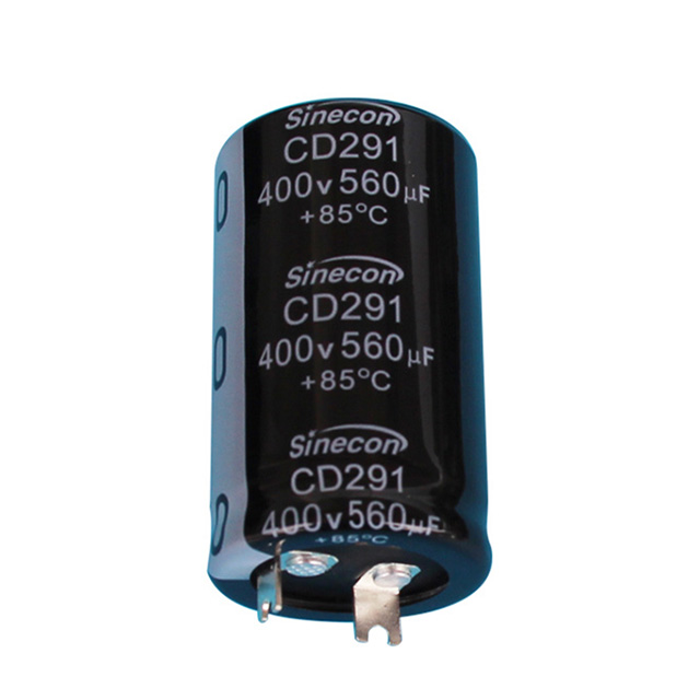
Industrial power electronics adds another layer: transients. Motor drives, inverters, welders, and charging equipment generate voltage spikes that a steady-state calculation never sees. Snap-in series built for high-voltage service, such as the CD297 ultra-high-voltage low-leakage series, combine a high rated voltage with low leakage current to absorb those conditions.
Warning. Never install a capacitor with a voltage rating lower than the part it replaces — even for a bench test. A transient you did not budget for will find that single weak link.
Ripple Current and ESR: Where the Heat Is Born
Ripple current is the most common reason an aluminum electrolytic capacitor dies in service. Every capacitor contains internal resistance — equivalent series resistance, or ESR — and ripple current flowing through it generates heat: P = I² × ESR. Because capacitor life is thermally driven, sustained current above the rating cooks the component from the inside.
Datasheets state the ripple rating at a defined frequency and ambient temperature — typically 105 °C at 100/120 Hz for line-frequency parts, or 100 kHz for switching-frequency parts. A capacitor on the DC bus of an inverter sees line-frequency ripple; the same physical part on a switch-mode output sees ripple at the converter's switching frequency. Those are different ratings, and treating them as interchangeable is how field failures begin.
ESR also shifts with temperature and frequency. A closer look at how equivalent series resistance behaves in aluminum electrolytic capacitors explains why two parts with the same microfarad value can perform very differently in the same circuit.
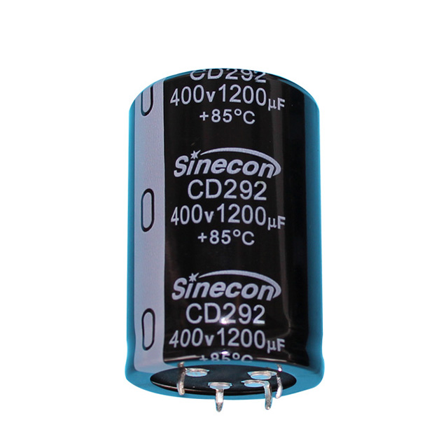
For DC-link positions where ripple dominates the thermal budget, choose a series built for the job. The snap-in CD293 high-ripple series spreads heat across a larger electrode area, which is why it appears in charging pile supplies and welding equipment.
Temperature and Lifetime: Read the Endurance Properly
Aluminum electrolytic capacitors age by losing electrolyte, and electrolyte loss follows temperature. The standard rule of thumb: lifetime roughly doubles for every 10 °C the core stays below the rated temperature, and halves for every 10 °C above it. A 105 °C capacitor operating at 85 °C is living about four times as long as the endurance rating suggests.
Two heat sources feed that core temperature: the ambient heat inside the enclosure and the self-heating of ripple current. Measuring the case temperature at worst-case load shows which one dominates and whether the design left real margin — the cheapest reliability improvement in the whole selection process.
Where service access is expensive — solar inverters, wind converters, telecom stations — long-life series justify their cost. Ratings of 5,000, 7,000, or more hours are common across radial, snap-in, and screw-terminal families.
Success. Measuring the case temperature at worst-case load is as close to free reliability as this field offers. If the case runs 10 °C below the rated maximum, the effective lifetime roughly doubles versus the datasheet endurance figure.
Form Factor and Physical Size: the Practical Constraints
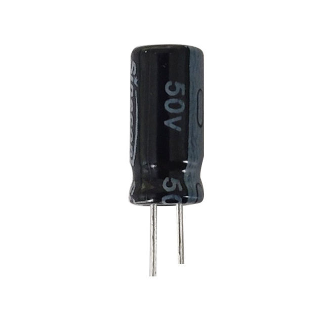
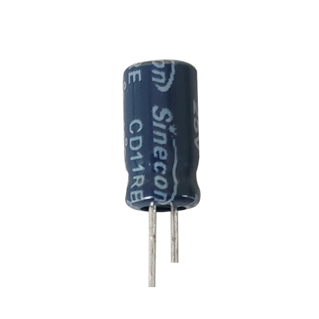
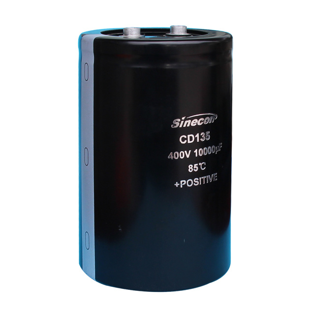
Form factor follows power level, assembly technology, and board space. Radial-lead capacitors are the default for power supplies, LED drivers, and audio circuits. Snap-in types take over in high-voltage DC-link positions where capacitance and ripple exceed what a radial part can comfortably deliver. Screw-terminal capacitors allow bolted bus-bar connections, making them the standard for inverter DC links and UPS ride-through storage.
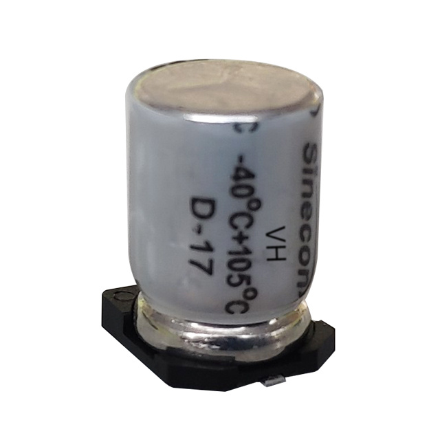
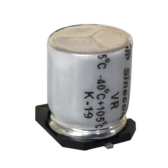
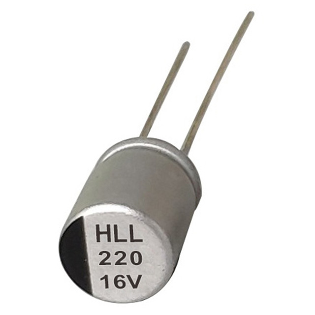
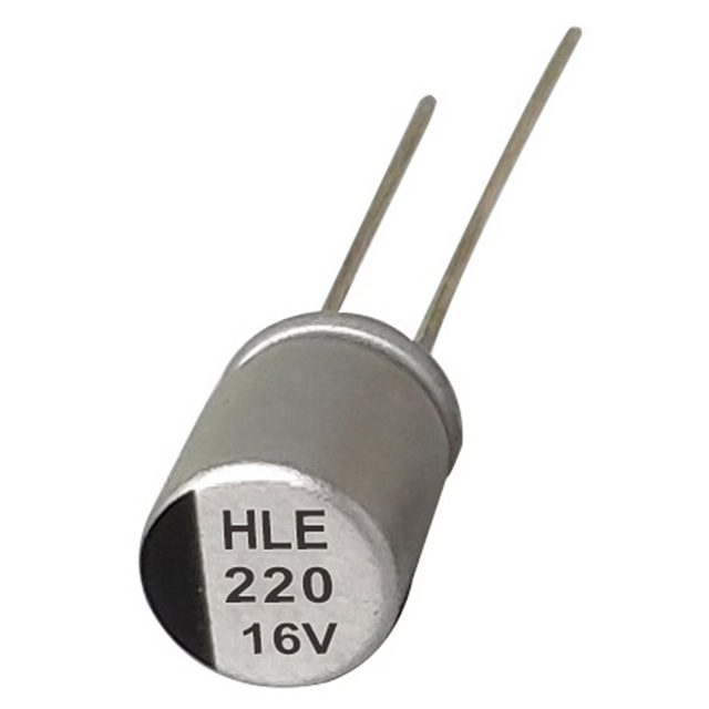
On automated lines, SMD capacitors eliminate through-hole processing and shorten assembly time. Polymer SMD types add a low-ESR advantage at high frequency, which suits compact adapters and telecom modules. The HDE series of surface-mount polymer capacitors is built for small sizes with low ESR and high ripple at low voltage — useful where board space is tight and switching frequencies are high.
Physical size remains the final gate. A 400 V 470 µF snap-in part shares almost nothing with a 16 V 470 µF SMD part except the microfarad notation. A sizing chart that ignores case dimensions has not left the office.
A Sizing Workflow That Holds Up in Production
The order of decisions matters. Voltage first, because a wrong voltage rating fails earliest. Capacitance second, because it shapes circuit performance. Ripple and ESR next, because they control the thermal picture. Temperature and form factor last, because they decide whether the part fits its environment and its production process.
- Define worst-case conditions: maximum DC bus voltage, ambient temperature range, and the ripple current waveform at the capacitor.
- Derate the voltage to about 80 percent of rated, then move to the next standard class — 35 V to 450 V and above.
- Calculate the required capacitance from the governing requirement — hold-up time, ripple voltage, or decoupling impedance — and apply the tolerance to the worst-case value.
- Compare the expected ripple current with the series rating at your frequency and ambient. If the margin is thin, move up a case size or switch to a high-ripple series.
- Check ESR or impedance at the switching frequency for output and decoupling positions.
- Estimate lifetime with the 10 °C rule. If the result falls below the design life, raise the voltage class, reduce ripple, or choose a long-life series.
- Confirm that the case size, terminal style, and mounting method suit the board and the assembly line.
Used consistently, this workflow prevents the recurring failure mode of industrial electronics: a capacitor that is electrically right and thermally wrong. The series families at the manufacturer's site are organized by form factor, a practical way to compare candidates once the constraints are known.
Danger. Do not release a design where ripple current exceeds the series rating at the worst-case ambient. The failure will be intermittent, temperature-dependent, and visible at customer sites rather than in the lab.
Sizing with Intent
A capacitor sizing chart is a good servant and a poor master. It hands you a plausible microfarad value and expects the engineer to bring everything else: the voltage margin, the ripple budget, the ESR at operating frequency, the endurance at the real temperature, and the mechanical fit. When those decisions are deliberate, the difference between a capacitor that fails within a year and one that serves for a decade stops being luck and becomes a design decision.