 English
 русский
 Tiếng Việt
 Español

How Do You Read Capacitor Values?
A capacitor's printed marking is the shortest datasheet you will ever hold. This guide decodes capacitance codes, unit conversions, voltage ratings and temperature markings before the wrong part reaches your bill of materials.
Two components arrive on the same inspection bench. One is a radial aluminum electrolytic capacitor printed in plain language: 470 µF, 25 V, 105 °C. The other is a small ceramic disc carrying nothing but "104". Both are perfectly readable, provided you recognize which marking system is in front of you.
The short answer comes first. Large capacitors, aluminum electrolytics above all, print their values directly in microfarads together with rated voltage, tolerance, temperature and a polarity stripe. Small ceramic and chip capacitors compress the same information into a numeric code: the first two digits are the significant figures, the third digit is the number of zeros, and the result reads in picofarads. A part marked 104 is therefore 10 followed by four zeros, which is 100,000 pF, or 0.1 µF. Everything else on the body refines that basic reading, and this article works through each layer in the order a buyer or design engineer actually needs it.
Start by Identifying the Marking System
Classify the part before decoding anything. If the body carries a unit, such as µF, MFD or a V rating, the value is printed directly and no decoding is required. If it shows two to four bare digits, you are almost certainly looking at a picofarad code. That single distinction eliminates most bench errors.
What aluminum electrolytics print directly
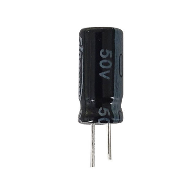
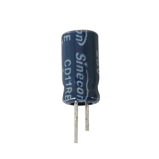
Aluminum electrolytic capacitors offer the most generous printing space in the component world, and series manufacturers use it. A standard radial part states its core parameters in full, which makes these the easiest components to verify at incoming inspection.
- Capacitance in microfarads (µF)
- Rated voltage in volts (V)
- Tolerance, typically ±20% on standard series
- Temperature category, usually 85 °C or 105 °C
- A polarity stripe that marks the negative lead
Warning. On aluminum electrolytic capacitors the stripe marks the negative terminal, not the positive. Installing the part reversed applies reverse voltage to the oxide dielectric and can force the pressure vent open within minutes of power-up.
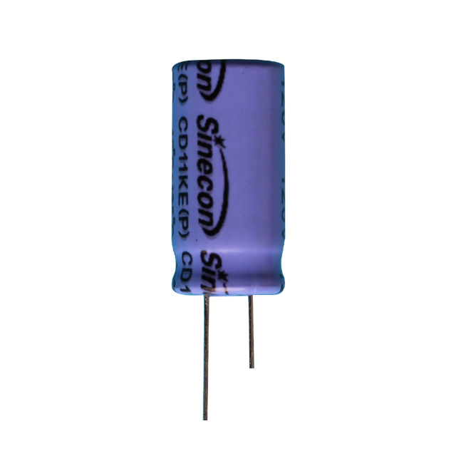 CD11KE Low Voltage Radial Aluminum Electrolytic CapacitorA high-temperature radial electrolytic rated up to 125°C and 5000 hours with low impedance. Worth checking when polarity markings and safe installation matter in long-life power circuits.View Product →
What compact codes hide
Ceramic discs, film boxes and chip capacitors are too small for full sentences, so they use compressed notation: the three-digit code, occasional two-digit markings, the letter R as a decimal point, and shorthand such as 4n7. The next section gives you the complete decoding rule.
Decoding the Three-Digit Code, Step by Step
The rule is consistent across the industry. The first two digits are the significant figures of a value in picofarads; the third digit tells you how many zeros follow. Take the first two digits, append the zeros, then convert the unit if your workflow thinks in nanofarads or microfarads.
| Code | Decoded as | In pF | In nF | In µF |
|---|---|---|---|---|
| 104 | 10 + four zeros | 100,000 | 100 | 0.1 |
| 224 | 22 + four zeros | 220,000 | 220 | 0.22 |
| 472 | 47 + two zeros | 4,700 | 4.7 | 0.0047 |
| 105 | 10 + five zeros | 1,000,000 | 1,000 | 1.0 |
| 331 | 33 + one zero | 330 | 0.33 | 0.00033 |
Info. 104 is the marking you will meet most often on digital boards: 0.1 µF (100 nF) decoupling capacitors sit beside nearly every integrated circuit's power pin.
A letter after the code describes tolerance rather than capacitance: J means ±5%, K means ±10% and M means ±20%, so 104 K is a 0.1 µF part with ±10% tolerance. A two-digit marking such as 22 carries no multiplier and simply means 22 pF, while 4R7 places the decimal point inside the number, giving 4.7 pF on a ceramic and 4.7 µF when printed on an electrolytic. Context always supplies the unit.
The Unit Ladder That Prevents Ordering Mistakes
Most reading errors are unit errors in disguise. The same 0.1 µF capacitor is described as 100 nF in European datasheets and 100,000 pF in code form, and a purchase order that mixes notations can return three different reels. The ladder is fixed: 1 µF equals 1,000 nF equals 1,000,000 pF. Convert everything into one unit before comparing quotations, and write the unit explicitly on every line item rather than trusting a bare number to be understood.
Voltage, Temperature and Load Life: the Ratings That Decide Fit
On an electrolytic can, the numbers beside the capacitance decide whether the part survives the application. Rated voltage is the continuous working limit, and conservative design keeps the real rail at 70–80% of it, so a 25 V capacitor is comfortable on a 12 to 18 V line. The reverse direction is never acceptable: operating above the printed voltage degrades the oxide layer, raises leakage and accelerates aging. The reasoning behind this is explained further in how the voltage rating of radial electrolytic capacitors impacts design.
The temperature figure is a statement about chemistry. A 105 °C marking means the electrolyte is formulated for that category temperature, and the load-life rating, whether 1,000, 2,000, 5,000 or 7,000 hours at rated conditions, describes how slowly capacitance, ESR and leakage drift. As a rule of thumb, every 10 °C reduction in actual operating temperature roughly doubles that lifetime, which is why a 105 °C series in a well-ventilated enclosure routinely outlives its printed hours. Screw-terminal parts built for inverters and industrial power stages advertise this figure openly.
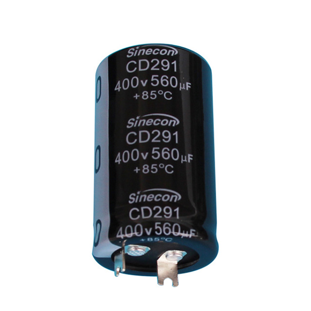
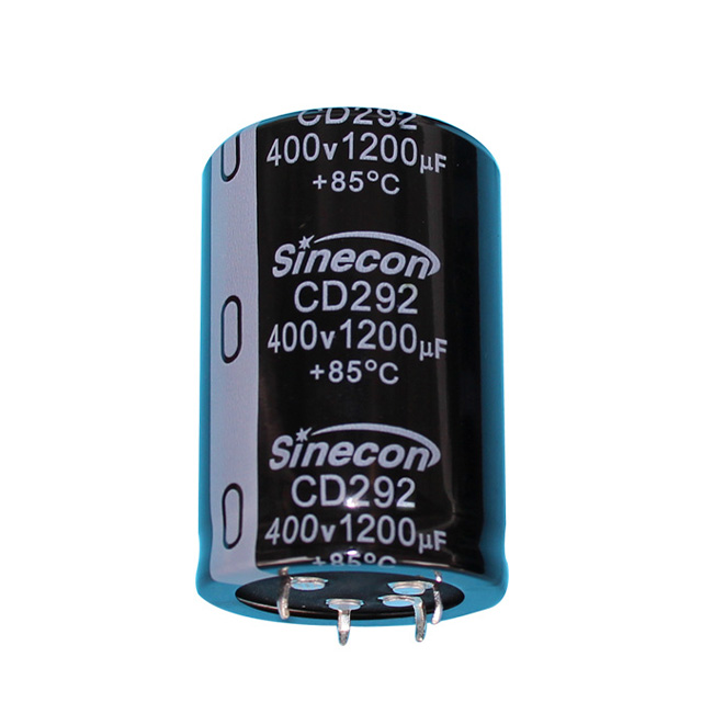
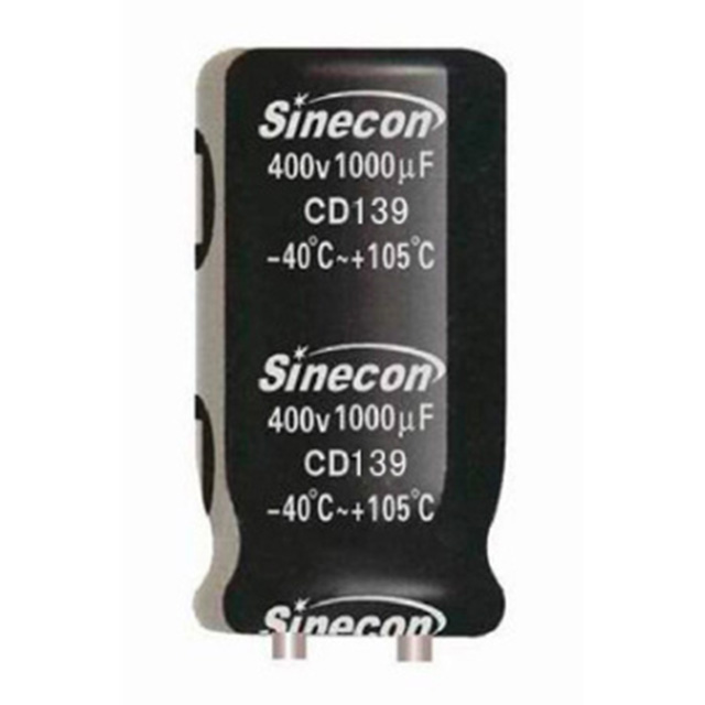 CD139 High Ripple Screw-Terminal Aluminum Electrolytic CapacitorThis 7000-hour terminal capacitor handles high ripple current for inverters and industrial power stages. Its load-life rating illustrates how 85°C series parts drift and age over time.View Product →
The capacitance printed on the body tells you what the part is. The voltage, temperature and load-life ratings tell you how long it will still be that part.
Success. Replacing a 470 µF / 25 V / 105 °C part with 470 µF / 35 V / 105 °C keeps the electrical value identical while adding voltage headroom. That is the safest substitution available to a buyer: same value, more margin.
Large Cans and SMD Parts: Reading the Edge Cases
Large snap-in and screw-terminal capacitors present the opposite problem: too much information. Beyond capacitance, voltage and temperature, the print often includes rated ripple current in amperes, ESR at 100 or 120 Hz, and a date code in year-week format. Treat the datasheet as authoritative and the can marking as the cross-check at goods-in.
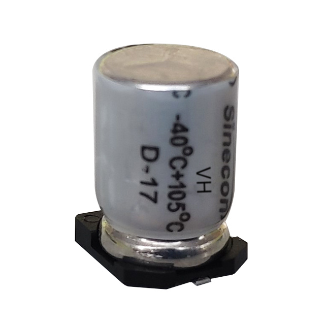
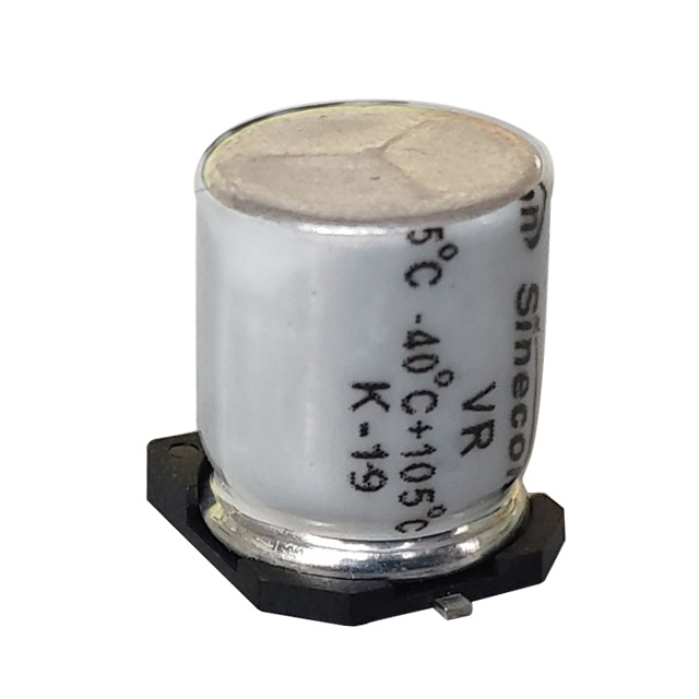
Chip aluminum electrolytics and SMD polymer types sit at the other extreme. Reflow-compatible footprints leave room only for abbreviated capacitance and voltage codes, and some values appear as two-character shorthand. Never decode a compact marking from memory: read it from the reel label or the series datasheet, confirm the marked polarity side before the part reaches the stencil, and check the ESR figure against the switching frequency of the application.
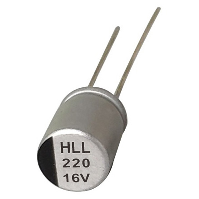
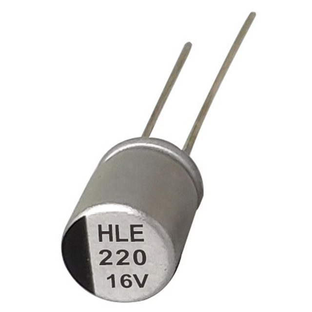
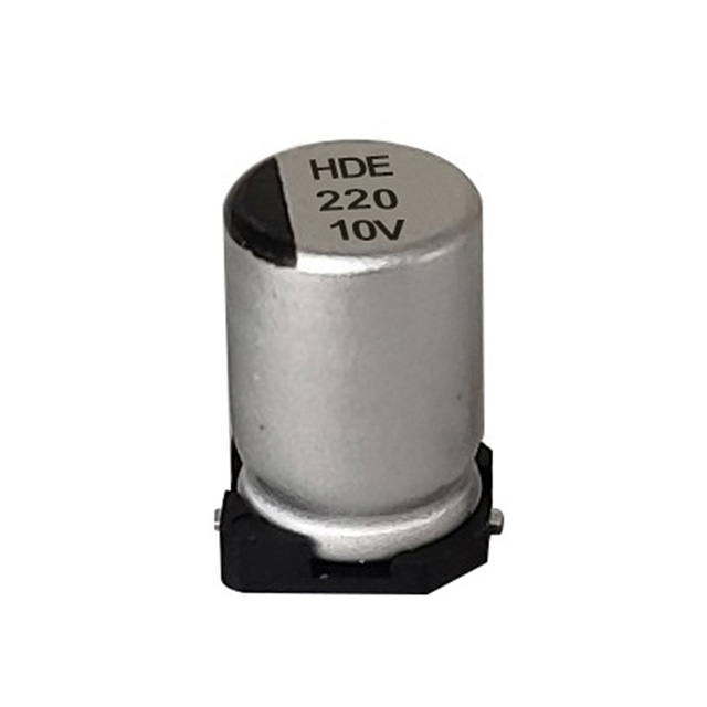 HDE Low ESR SMD Polymer Aluminum Electrolytic CapacitorA compact surface-mount polymer capacitor with low ESR and high ripple capability. Its ESR figure matters when substituting parts in switch-mode supplies, where matching capacitance alone is insufficient.View Product →
Danger. Matching microfarads alone is not enough in switch-mode supplies. An SMD replacement with significantly higher ESR will dissipate more heat at the same ripple current and fail early, even though the printed capacitance matches the part it replaces.
A Seven-Point Checklist Before You Confirm the Order
Run any incoming marking, or any quotation, through the same sequence:
- Write the unit on every line: 100 nF, 0.1 µF and 100,000 pF name the same part only when the notation is explicit.
- Decode the three-digit code and sanity-check the magnitude; 104 is 0.1 µF, never 104 µF.
- Read the tolerance letter (J ±5%, K ±10%, M ±20%) and match it to the circuit's real sensitivity.
- Check the rated voltage against the working rail with 20–30% derating.
- Match the temperature category and load-life hours to the product's actual thermal environment.
- Confirm polarity orientation and footprint for every electrolytic before the layout is released.
- For switching applications, compare ESR and ripple current, not just capacitance, and request batch-level test data from the supplier.
That final point deserves emphasis. Markings describe a design; process discipline decides whether every delivered batch matches the print. Established aluminum electrolytic manufacturers such as Nantong Xingchen Electron, which has produced these components since 1985, run MES-controlled production lines precisely so that the value you read on the can is the value inside every reel.
The Bottom Line
Reading capacitor values is a three-step habit: identify the marking system, decode the digits, then weigh the secondary ratings of voltage, tolerance, temperature and load life against the application. Practiced consistently, it turns the print on a capacitor body into the fastest datasheet you own, and it makes the conversation with your supplier shorter, because the part you order is the part your circuit was actually designed around.