 English
 русский
 Tiếng Việt
 Español

When it comes to high-frequency applications, Film Capacitors significantly outperform Radial Electrolytic Capacitors of the same capacitance value. This is not a marginal difference — it is a fundamental gap rooted in construction, materials, and electrical behavior. If you are designing circuits operating above 10 kHz, understanding this distinction is critical to making the right component choice.
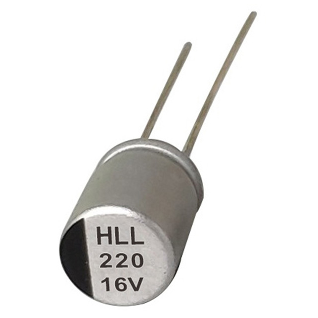
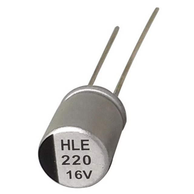
Radial Electrolytic Capacitors use a liquid or gel electrolyte between aluminum foil plates, which introduces parasitic inductance and relatively high Equivalent Series Resistance (ESR). Film Capacitors, by contrast, use a thin polymer dielectric (polyester, polypropylene, or polystyrene) that enables far lower ESR and superior high-frequency response. For engineers evaluating capacitors for switching regulators, audio crossovers, or RF filtering, these differences are decisive.
Understanding ESR: The Core High-Frequency Bottleneck
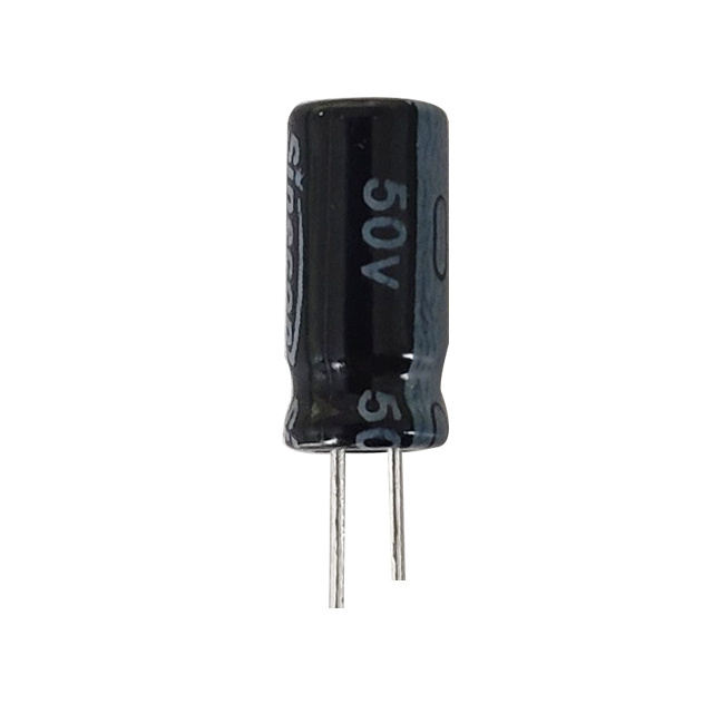
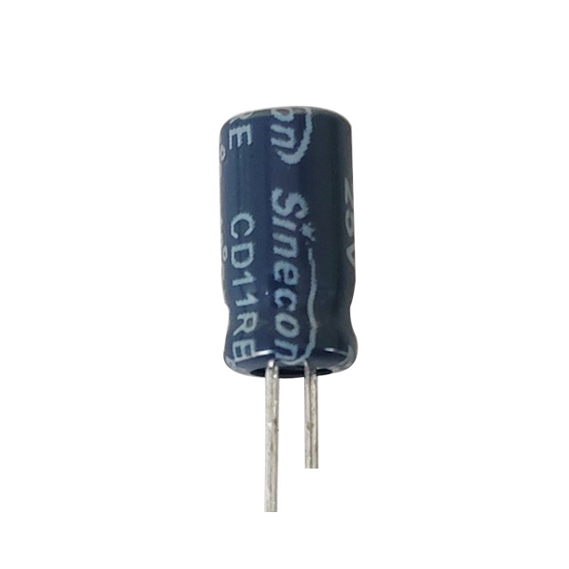
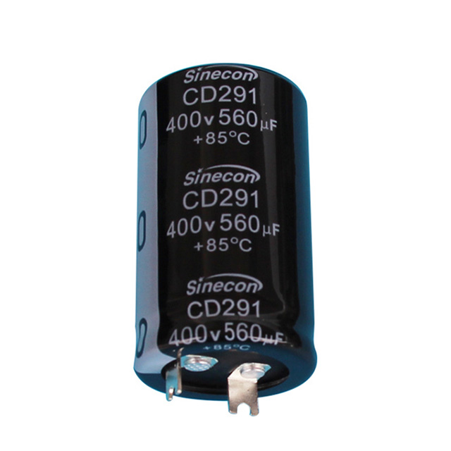
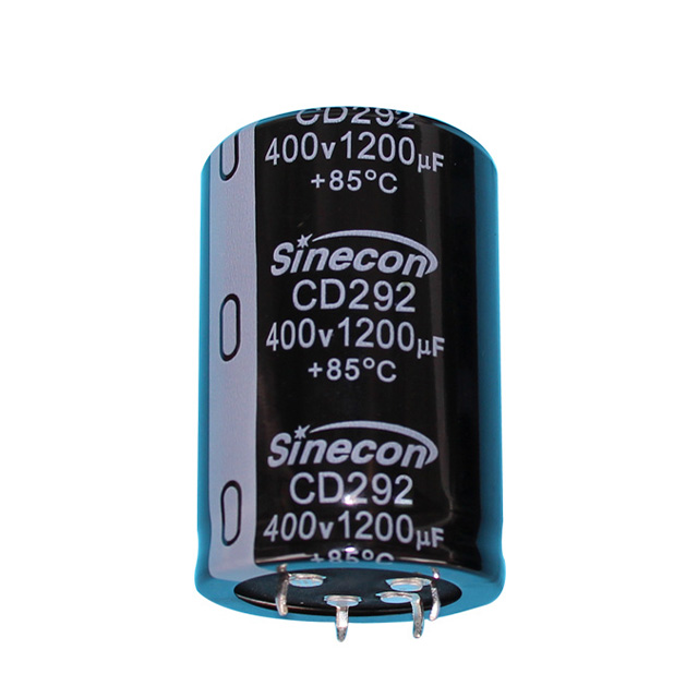
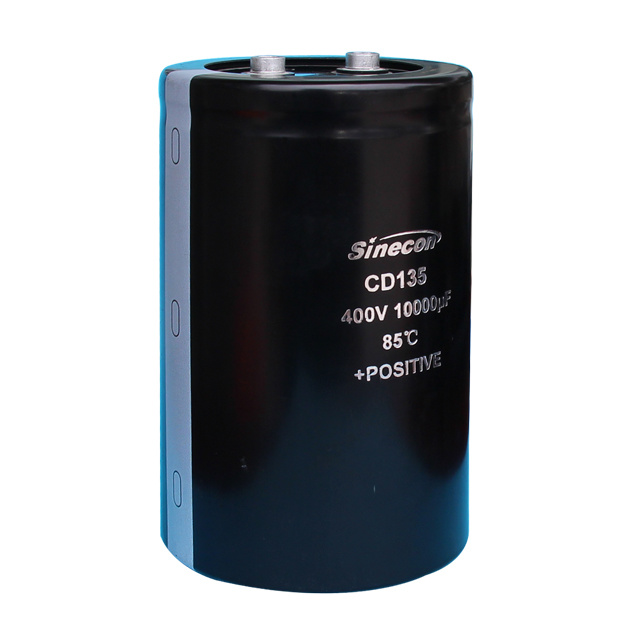
ESR is arguably the single most important parameter distinguishing these two capacitor types in AC and high-frequency environments. A standard Radial Electrolytic Capacitor rated at 100 µF / 50V typically exhibits an ESR in the range of 0.1 Ω to 1.0 Ω at 100 kHz, depending on quality grade and brand. Premium capacitors from manufacturers like Sinecon capacitors can push ESR lower, but the electrolytic construction still imposes a physical ceiling.
Film Capacitors of equivalent capacitance, such as a 100 µF polypropylene type, can achieve ESR values as low as 0.005 Ω to 0.02 Ω — often 20 to 100 times lower. This drastically reduces power loss (P = I² × ESR) during high-frequency ripple current handling, making film types far more efficient in demanding AC environments.
Self-Resonant Frequency: Where Each Capacitor Starts to Fail
Every capacitor has a Self-Resonant Frequency (SRF), beyond which it stops behaving as a capacitor and begins to act inductively. This is governed by the internal Equivalent Series Inductance (ESL). Below the SRF, the capacitor performs its filtering or bypassing function. Above it, impedance rises and performance degrades.
Radial Electrolytic Capacitors typically have their SRF in the range of 1 kHz to 500 kHz, depending on capacitance and lead length. A 1000 µF radial electrolytic may resonate at only 10–20 kHz. Film Capacitors, due to their tightly wound or stacked foil construction with minimal ESL, often achieve SRF values ranging from 1 MHz to over 10 MHz, making them far more suitable for high-frequency filtering and decoupling.
| Parameter | Radial Electrolytic Capacitor | Film Capacitor |
|---|---|---|
| Typical ESR (100 kHz) | 0.1 Ω – 1.0 Ω | 0.005 Ω – 0.02 Ω |
| Self-Resonant Frequency | 10 kHz – 500 kHz | 1 MHz – 10+ MHz |
| Typical ESL | 10 nH – 50 nH | 1 nH – 10 nH |
| Ripple Current Handling | Moderate | High |
| Capacitance Stability vs. Freq. | Poor above 100 kHz | Excellent up to several MHz |
| Polarized | Yes | No |
Impedance vs. Frequency: The Practical Performance Curve
When plotted on an impedance-frequency graph, the behavioral difference becomes visually stark. A Radial Electrolytic Capacitor's impedance curve shows a relatively steep rise after its resonance point, while a Film Capacitor maintains low impedance across a much broader frequency band.
For example, take a 10 µF capacitor from each type:
- At 1 kHz — both perform comparably, with impedance near their capacitive reactance values.
- At 100 kHz — the Radial Electrolytic begins showing elevated impedance due to ESR domination.
- At 1 MHz — the Radial Electrolytic is largely inductive; the Film Capacitor still filters effectively.
- At 10 MHz — Film Capacitors maintain usable impedance; Radial Electrolytics offer virtually no filtering benefit.
This is why engineers designing RF power amplifiers, inverters, or Class D audio amplifiers consistently choose Film Capacitors for high-frequency signal paths, even when their cost is higher per unit.
Ripple Current Tolerance Under High-Frequency Stress
In switching power supplies and motor drives, ripple current is a continuous thermal stressor. Radial Electrolytic Capacitors generate significantly more internal heat under the same ripple current conditions, due to their higher ESR converting AC energy into heat (P = I² × ESR). This leads to accelerated electrolyte evaporation and premature failure.
Manufacturers of quality capacitors, including Sinecon capacitors, publish ripple current ratings that derate with increasing frequency and temperature. A typical 105°C-rated Radial Electrolytic Capacitor at 100 kHz may only tolerate 60–70% of its rated 120 Hz ripple current, while a polypropylene Film Capacitor can handle its full rated current well into the MHz range without significant thermal rise.
This is a critical consideration when designing:
- PWM-driven motor controllers (switching at 20–100 kHz)
- DC-DC boost/buck converters
- Solar inverter output stages
- UPS filter circuits
Where Radial Electrolytic Capacitors Still Hold an Advantage
Despite their high-frequency limitations, Radial Electrolytic Capacitors are not obsolete — they remain indispensable in the right applications. Their primary advantages are:
- High capacitance density: Achieving 1000 µF to 100,000 µF in a compact through-hole package is still practically impossible with film types.
- Cost efficiency: For bulk energy storage at 50/60 Hz (e.g., mains rectifier smoothing), Radial Electrolytics offer the best cost-per-microfarad ratio by a wide margin.
- Low-frequency filtering: At frequencies below 1 kHz, Radial Electrolytic Capacitors perform adequately and are the industry standard for power supply bulk capacitance.
- Size for size: A 100 µF / 50V Film Capacitor may be 3–5× the physical volume of its electrolytic equivalent, making board integration more complex.
In modern PCB designs, experienced engineers often combine both types — using Radial Electrolytic Capacitors for bulk hold-up capacitance at low frequencies and placing Film Capacitors or SMD capacitors in parallel for high-frequency noise suppression. This hybrid strategy delivers the best of both worlds without sacrificing board space or budget.
SMD Alternatives and the Role of Package Format
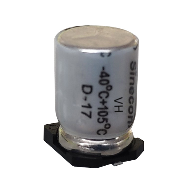
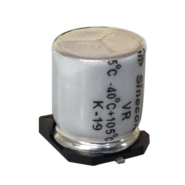
For high-frequency designs where PCB space is at a premium, SMD capacitors — including SMD electrolytic and SMD film variants — offer a compelling advantage. Their shorter lead lengths and smaller parasitic inductance inherently improve high-frequency performance compared to through-hole Radial Electrolytic Capacitors. A surface-mount 10 µF electrolytic may exhibit ESL below 2 nH, compared to 20–50 nH in a leaded radial equivalent.
Manufacturers such as Sinecon capacitors produce both radial and SMD capacitors lines, allowing designers to choose the best package for each stage of their circuit — bulk storage using radial electrolytics and high-frequency decoupling using SMD capacitors placed as close as possible to the IC power pins.
Practical Design Recommendations
Based on the performance data above, here is a concise decision framework for selecting between Radial Electrolytic Capacitors and Film Capacitors:
- Below 10 kHz / bulk energy storage: Use Radial Electrolytic Capacitors. They are cost-effective, compact for high capacitance, and more than adequate at low frequencies.
- 10 kHz – 1 MHz filtering and bypassing: Prefer Film Capacitors or low-ESR SMD capacitors. The reduction in ESR and improved SRF will noticeably reduce noise and improve efficiency.
- Above 1 MHz (RF, Class D amplifiers, high-speed logic decoupling): Film Capacitors or MLCC SMD capacitors are mandatory. Radial Electrolytic Capacitors are inductive in this range and will worsen performance.
- Mixed-signal or noise-sensitive circuits: Place a small Film or ceramic SMD capacitor (100 nF – 1 µF) in parallel with each Radial Electrolytic Capacitor to cover the high-frequency spectrum the electrolytic cannot handle.
- Automotive and industrial environments: Evaluate ripple current derating carefully. Choose 105°C-rated Radial Electrolytic Capacitors or switch to Film Capacitors where continuous high-frequency ripple exceeds the electrolytic's thermal limit.
Radial Electrolytic Capacitors are reliable, cost-effective workhorses for low-frequency energy storage and smoothing, but they are fundamentally limited in high-frequency applications by their elevated ESR, higher ESL, and lower self-resonant frequency. Film Capacitors of the same capacitance value offer dramatically superior high-frequency performance — often 20–100× lower ESR and SRF values up to 10 MHz or beyond.
For modern power electronics, audio systems, and RF circuits, the best approach is not a binary choice but a strategic combination: Radial Electrolytic Capacitors for bulk capacitance and Film or SMD capacitors for high-frequency suppression. Understanding where each type excels allows engineers to design circuits that are efficient, reliable, and cost-optimized across the full operating frequency range.