 English
 русский
 Tiếng Việt
 Español


Capacitor Power Formula: Energy, Ripple, and the Heat You Cannot See
Stored energy is the easy number. Ripple current through ESR is the one that decides how long a capacitor actually survives on a board.
A 470 µF, 400 V snap-in capacitor holds 37.6 joules at full charge. Release that energy in 10 milliseconds and the average power during the pulse is about 3.8 kW. Yet the same part may be rated for only 3 A of RMS ripple at 100 Hz, which at 0.3 Ω of ESR becomes roughly 2.7 W of internal heat. One component, two power figures three orders of magnitude apart.
The short answer: a capacitor stores energy as E = 0.5 × C × V², releases it at a rate set by how quickly the voltage is allowed to fall, and dissipates P = I² × ESR whenever alternating current flows through its internal resistance. In AC circuits a fourth relationship appears, the reactive power Q = V² × 2πfC, which is not consumed but still pushes real current through foils, tabs, and electrolyte.
This article works through each formula with numbers rather than symbols, then links the results to package choices so the calculation ends at a part decision.
Voltage is squared in the energy formula, so it buys storage more cheaply than capacitance. Ripple current is squared in the heating formula, so it shortens life far more aggressively than load current. Most field failures trace to the second effect.
Five Relationships Behind Every Capacitor Power Question
Searching for a single capacitor power formula usually means one of five relationships is needed. They answer different questions, and mixing them up is a common cause of parts that run hot or fail early.
| Quantity | Formula | Unit | What it constrains |
|---|---|---|---|
| Stored energy | E = 0.5 × C × V² | joule (J) | Holdup time and discharge energy |
| Usable energy | E = 0.5 × C × (V1² − V2²) | joule (J) | Energy available between two voltage limits |
| Average discharge power | P = 0.5 × C × V² / t | watt (W) | Pulse power delivered by a storage bank |
| Charging current | I = C × dv/dt | ampere (A) | Inrush current and rectifier stress |
| Ripple heating | P = I² × ESR | watt (W) | Core temperature and service life |
| Reactive power | Q = V² × 2πfC | var | AC current the part must carry |
Watch the exponents. Voltage squared means a 450 V capacitor stores 81 times the energy of a 50 V part of the same capacitance. Current squared means doubling ripple current quadruples the heat. Those two exponents explain most of what you measure on a bench.
Stored Energy: Why Voltage Beats Capacitance
E = 0.5 × C × V² rewards voltage far more generously than capacitance, and the numbers make the point quickly:
- 100 µF at 50 V stores 0.13 J
- 100 µF at 450 V stores 10.1 J
- 470 µF at 400 V stores 37.6 J
Matching one 450 V, 100 µF part with 50 V parts would take about 81 of them in parallel, with more board area, more leakage paths, and more solder joints carrying the same charge.
Usable energy is always smaller than stored energy. A 470 µF bank that discharges from 400 V down to 300 V gives up only 16.5 J, about 44 percent of what it holds. When a holdup requirement is written against a minimum bus voltage, calculate between the two limits instead of from full charge to zero, or the design will be oversized by a wide margin.
Discharge Power and Inrush: One Formula, Two Directions
P = E / t converts stored energy into an average power figure. A 37.6 J bank released over 10 ms delivers 3.8 kW; the same bank released over 5 seconds delivers 7.5 W. Neither number says much about survival, because average power over a pulse says nothing about peak current.
The real constraint is I = C × dv/dt. Charging that 470 µF capacitor from 0 V to 400 V in 1 ms demands 188 A from the source. Stretch the same rise to 100 ms and the current falls to 1.9 A, a hundredfold reduction from nothing more than a slower ramp.
Raising capacitance adds stored energy, but it also raises inrush current in direct proportion. Sometimes the cheaper design change is a softer charging path, not a bigger capacitor.
This is why pre-charge resistors, NTC thermistors, and soft-start stages exist, and why surge ratings matter as much as capacitance in rectifier front ends. Surge-resistant and lightning-resistant families, such as the CD296 snap-in type, are specified for exactly these short, hostile dv/dt events.
Ripple Current and ESR: The Formula That Ages Capacitors
P = I² × ESR is the least glamorous relationship and the one that ends product lifetimes. Ripple current from rectification, switching, or inverter pulses passes through foil and electrolyte, and the heat it produces has only the can surface as an escape route.
| Ripple current (A rms) | ESR (Ω) | Internal heat (W) | Typical setting |
|---|---|---|---|
| 0.5 | 0.50 | 0.13 | Bias supply with a small radial part |
| 1.5 | 0.20 | 0.45 | General-purpose adapter output |
| 3.0 | 0.05 | 0.45 | PFC stage using a snap-in part |
| 6.0 | 0.02 | 0.72 | Inverter DC link with screw terminals |
The highest-current row generates less heat than the adapter row, because ESR fell by an order of magnitude. Over time the relationship runs in reverse: ESR climbs as electrolyte migrates and dries, which raises dissipation, which accelerates drying. This note on ESR and its impact on capacitor behavior covers how frequency, temperature, and age move that number.
Temperature is where ripple heat becomes a lifetime figure. General-purpose aluminum electrolytics are often rated 2,000 hours at 105 °C, while long-life series run 5,000 to 7,000 hours. As a working rule, every 10 °C drop in core temperature roughly doubles expected life. Cutting ripple current by 30 percent halves dissipation and buys a disproportionate amount of time.
Ripple ratings are quoted at a reference frequency, often 100 kHz or 120 Hz. At lower frequencies the permitted ripple current is smaller and a datasheet multiplier must be applied. Using a 100 kHz rating at 120 Hz without correction overstates the part's capability.
The AC View: Reactive Power Flows Without Being Consumed
Q = V² × 2πfC describes the reactive power a capacitor exchanges with an AC source. Nothing is dissipated, but the current is real. At 400 V and 50 Hz, a 470 µF capacitor presents about 6.8 Ω of reactance and draws roughly 59 A rms through its own terminals.
That single number explains why polarized electrolytic capacitors are never connected directly across mains lines, and why AC-rated film capacitors exist for that duty. Inside a DC link the same relationship works in your favor: at 100 kHz the reactance of a 470 µF part collapses to about 0.0034 Ω, so it behaves as a near short for switching ripple.
For local decoupling, the practical version is written per edge. A 10 µF polymer capacitor holding a 1 V rail while the load steps in 1 µs has to supply a 10 A transient in that instant, a value set by capacitance and slew rate rather than by average load.
From Formula to Part: Matching Numbers to Families
Once energy, inrush, and ripple figures are known, selection becomes a packaging decision. Voltage class and ESR narrow the field quickly, and what remains is choosing a construction that can move heat out of the winding. We build aluminum electrolytic capacitors across radial, SMD, polymer, snap-in, and screw-terminal formats, so a calculated ripple figure usually maps onto our power-conversion capacitor families without compromise on package type.
Snap-in construction for bulk DC links
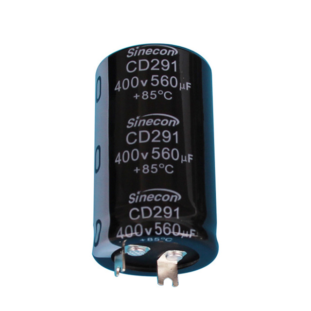
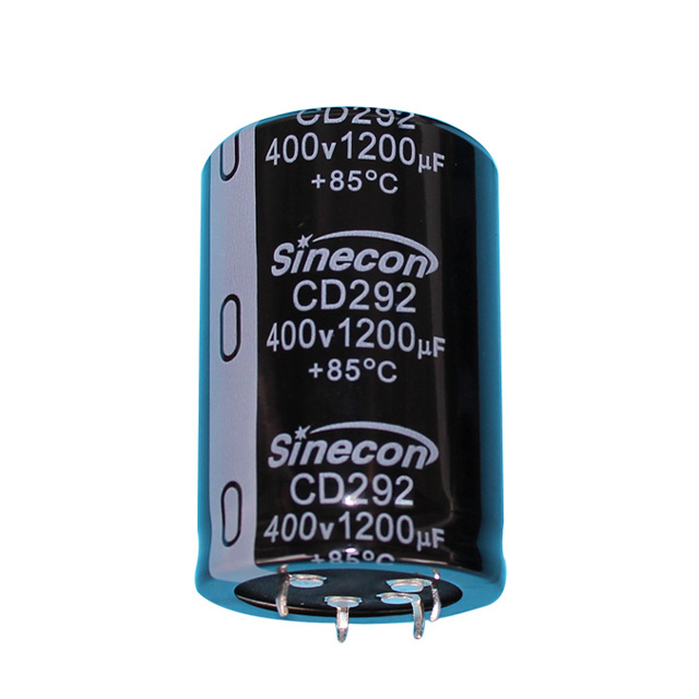
Above roughly 200 V and 100 µF, snap-in capacitors carry most of the bulk storage in PFC stages, inverters, and switching supplies. A 450 V, 470 µF snap-in typically absorbs several amperes of 100 Hz ripple while keeping ESR in the tens of milliohms. The CD293 high-ripple standard series is built for that duty, and the CD292 four-pin version adds stability where vibration is present.
Screw terminals for long-life energy storage
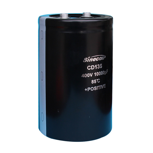
Welding equipment, UPS systems, solar and wind inverters, and motor-starting circuits push ripple ratings and service expectations higher at the same time. Screw-terminal capacitors offer larger cans, better heat removal, and higher current capability. The CD139 series is rated for 7,000 hours with high ripple capability, the CD60 is a standard choice for motor starting, and the CD13L is tuned for air-conditioning duty.
Polymer construction for fast, low-ESR paths
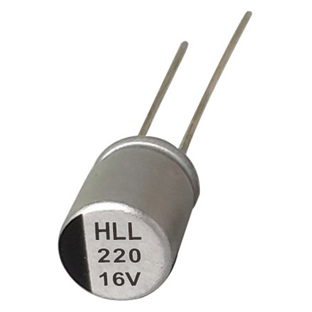
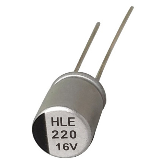
When dv/dt is steep and switching frequency is high, ESR and equivalent inductance dominate the impedance. Solid polymer construction removes the drying-out failure mode and keeps ESR low across temperature. In the lead-type polymer range, the HLL series targets high ripple with low ESR, while the HLR version extends rated life to 5,000 hours for designs where service access is difficult.
Corrections That Real Circuits Add to the Formula
Datasheet values are measured under defined conditions. Four corrections keep a calculation honest:
- Capacitance tolerance of ±20 percent means stored energy can land 20 percent below the nameplate value, so holdup time should be designed against the minimum.
- ESR is a maximum figure, usually quoted at 100 kHz and 20 °C. At −40 °C it may be several times higher, which matters for outdoor equipment.
- Ripple ratings are tied to a reference frequency and to the maximum category temperature; both need adjustment for the real operating point.
- ESR roughly doubles by end of life, so dissipation at hour zero is not the worst case. Derating to about 80 percent of rated voltage further reduces leakage stress.
Multiply calculated dissipation by the thermal resistance from core to ambient. If the result puts the core more than 10 °C above the ambient used in the life rating, recalculate expected life before the bill of materials is fixed.
An undersized ripple rating rarely fails immediately. Electrolyte dries slowly, ESR climbs, heat rises further, and capacitance falls. The symptom appears months later as unexplained shutdowns under load.
Keeping the Numbers on Your Desk
The capacitor power formula is three equations wearing one name. E = 0.5 × C × V² defines how much energy the part holds, P = E / t and I = C × dv/dt define how fast it can move, and P = I² × ESR defines what that movement costs in heat and service life. Reactive power adds the AC current that flows without ever being consumed.
Work through them in that order — energy, rate, heat — and package selection follows: snap-in for bulk DC links, screw-terminal for high-energy long-life storage, polymer for fast low-ESR paths, and radial or SMD for everything else on the board. The formula never changes with the package. Only the thermal path does.