 English
 русский
 Tiếng Việt
 Español


Voltage Capacitors in Parallel: What the Bank Rating Really Is
A practical guide to capacitance, current sharing and the voltage ceiling that governs any parallel capacitor bank.
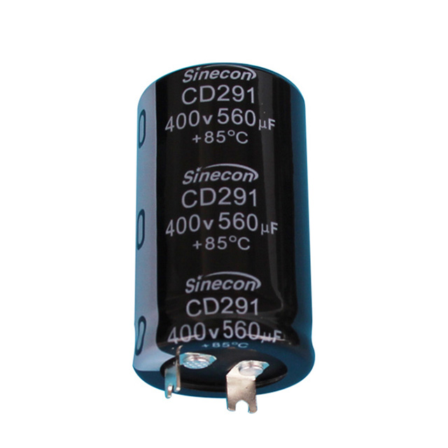
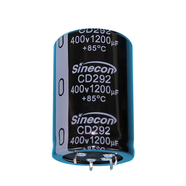
Six 470 µF snap-in capacitors sit in a row across the 400 V DC link of a charging module. The drawing calls the group a 2,820 µF bank, and everyone reads that number as harmless arithmetic. Then someone asks what happens if two of the six positions are populated with 350 V parts instead of 450 V, and the room goes quiet.
Here is the answer before the reasoning. Capacitors in parallel all see the same voltage, their capacitances add together, their equivalent series resistance drops, and the voltage rating of the entire bank equals the lowest rating in the row. Not the average, not the highest, and not something the layout can improve.
That single sentence decides whether a bank survives a surge event or vents electrolyte on a hot afternoon. What follows is what actually changes when capacitors are placed in parallel, what does not change at all, and which details tend to bite during qualification.
One Voltage, Shared Charge: What Parallel Connection Changes
In a parallel arrangement the terminals are tied together, so every capacitor sees the same potential difference. Charge does not divide equally; it divides in proportion to capacitance. At 48 V, a 1,000 µF capacitor stores ten times the charge of the 100 µF capacitor sitting beside it, while both are stressed by exactly the same voltage.
The arithmetic is simple. Total capacitance is the sum of the individual values, and stored energy follows that total:
- C total = C1 + C2 + ... + Cn
- Energy stored = 1/2 x C total x V squared
- Equivalent resistance and inductance combine as reciprocals, so they fall as parts are added
| Property | Series bank | Parallel bank |
|---|---|---|
| Total capacitance | Reciprocals add | Values add directly |
| Voltage across each part | Divides; the smallest capacitor takes the largest share | Identical for every capacitor in the bank |
| Voltage rating of the group | Adds, provided balancing is in place | Equals the lowest single rating |
| Balancing hardware | Usually required | Not required |
| Typical role | High-voltage strings and stacked links | Bulk storage, decoupling, ripple sharing |
| Weakest-part risk | Overvoltage on the smallest capacitor | Overheating in the lowest-ESR capacitor |
The Voltage Rating of a Parallel Bank, Stated Plainly
Capacitance adds in parallel. Voltage rating does not. The bank simply inherits the lowest number in the row.
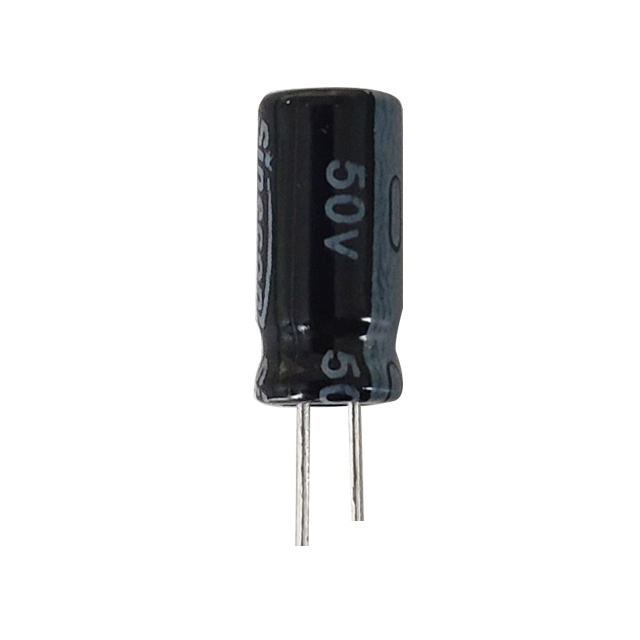
A 63 V capacitor and a 35 V capacitor wired in parallel form a 35 V bank. The 63 V part runs far below its own ceiling, which is harmless for the capacitor and misleading for anyone reading the schematic note.
There is a second layer to the rule: rated voltage is not working voltage. Aluminum electrolytics are normally operated with margin. Sitting at 80 percent of the rated voltage is a common baseline for room-temperature designs; high-ripple or 105 °C designs often move toward 70 percent, and long-life industrial products can go lower still.
Surge ratings are not working voltages. A part that tolerates a short surge at its rated voltage should not be asked to live there continuously, and a parallel bank offers no shared margin that a single capacitor would not have.
| Rated voltage | 80 percent target | 70 percent target |
|---|---|---|
| 25 V | 20 V | 17.5 V |
| 35 V | 28 V | 24.5 V |
| 50 V | 40 V | 35 V |
| 63 V | 50 V | 44 V |
| 100 V | 80 V | 70 V |
| 200 V | 160 V | 140 V |
| 400 V | 320 V | 280 V |
| 450 V | 360 V | 315 V |
Why Parallel Banks Earn Their Board Space
Parallel connection divides resistance and inductance in the same way resistors combine. Five capacitors with 100 milliohms of ESR behave, as a group, like a 20 milliohm component. Lower equivalent resistance means less internal heating at a given ripple current, and less heating means longer life; the familiar rule of thumb is that every 10 °C reduction in core temperature roughly doubles service life.
Ripple current does not divide evenly, though. It splits according to impedance, so the lowest-ESR capacitor in the bank carries the largest share and runs the hottest. Checking only the bank's total ripple rating, instead of the per-part share, is how a single warm can appears under a thermal camera.
Before the layout is frozen, it is worth revisiting how ESR shapes ripple current and heat in an aluminum electrolytic capacitor, because that relationship sets the real limit of a parallel bank.
Mismatched Parts and the Stress That Migrates
Two capacitors from the same production run can differ by 20 percent in capacitance and by considerably more in ESR, especially when they come from different lots or different storage conditions. In a parallel bank that spread shows up as unequal current sharing rather than unequal voltage.
The failure sequence is worth spelling out, because it is counterintuitive. The lowest-ESR part carries the most ripple current and runs hottest. Heat dries the electrolyte, which raises ESR and lowers capacitance. As its ESR climbs, its share of the current falls, and the remaining capacitors absorb the difference. The bank rarely fails all at once; it rotates stress from part to part until one can vents.
Never mix voltage ratings inside one parallel bank, even during prototype builds. If a bank must combine series or lots, measure ESR before assembly and freeze the bill of materials through qualification, because a silent supplier change can shift the current balance in ways no schematic will show.
Copper Matters as Much as Capacitance
Trace and busbar resistance of a few milliohms is irrelevant at 1 A and decisive at 100 A. If the copper path to one capacitor is 30 mm longer than the path to its neighbour, the current split will follow the copper, not the datasheet. Symmetric layouts, equal-length branches and a shared star point are the standard fixes.
The same logic applies at high frequency, where equivalent series inductance dominates. Parallel capacitors reduce the loop inductance of the bank only when they share a compact return path; spread them across a wide loop and the benefit evaporates.
This is why low-ESR polymer parts and bulk electrolytics are frequently used together: the polymer handles the fast edge, the electrolytic covers the slower energy demand, and the copper decides whether either does its job.
A Practical Checklist for Parallel Banks
Most parallel bank problems trace back to five decisions that are made early and rarely revisited. The list below is the version that holds up in production.
- Set the bank voltage from the lowest-rated capacitor, then apply derating: 80 percent of rating as a floor for room-temperature designs, closer to 70 percent for high-ripple or high-temperature duty.
- Keep one rating, one series and ideally one lot across the bank. Mixed lots mean mixed ESR, and mixed ESR means mixed current.
- Size ripple per capacitor rather than per bank, and assume the lowest-ESR part will take more than its arithmetic share.
- Lay copper out symmetrically, because equal path lengths matter more than total copper area once currents rise.
- Confirm the thermal picture under worst-case load with a camera, not only with a spreadsheet.
- Decide in advance what a failed capacitor is allowed to do. Venting, shorting and gradual capacitance loss are three different events with three different consequences.
When More Capacitors in Parallel Stop Helping
Parallel connection raises capacitance. It never raises voltage capability, which is the job of a series string, and series strings need balancing resistors because capacitance tolerance turns directly into voltage imbalance.
Stored energy also grows with the bank. A 2,820 µF bank charged to 400 V holds roughly 226 joules, all of it available to a fault path, a dropped tool or a technician's hand. Bleeder resistors, a defined discharge time and short-circuit protection are part of the bank, not optional extras.
One more subtlety is worth knowing. Paralleling two groups of very different capacitance values can create an anti-resonance between them, where the combined impedance rises at a specific frequency instead of falling. It rarely matters in bulk energy storage, and it matters a great deal in high-frequency decoupling networks.
Stored energy is the hazard in any parallel bank. Confirm bleeder sizing, discharge time and lockout procedure before first power-up, and treat a capacitor that has not been discharged as live.
Three numbers decide whether a parallel bank behaves: the voltage rating, which is the lowest rating in the row; the capacitance, which is the sum; and the ESR, which is the reciprocal of the sum of reciprocals. The capacitor carrying the most ripple current is the one with the least resistance, and it will also be the one running hottest.
Get those right, keep the copper symmetric and hold the bill of materials steady, and parallel banks do precisely what designers ask of them: they lower impedance, spread heat and buy years of service life for the cost of a few extra components. Because the bank is only ever as strong as the weakest part in it, an aluminum electrolytic capacitor supplier that can document tolerance and lifetime data across one series makes that calculation far easier to defend.