 English
 русский
 Tiếng Việt
 Español

Component Engineering — Power Electronics
Ripple Current, Reconsidered
Why an aluminum capacitor and a film capacitor age so differently under the same electrical stress — and what that means for the circuits you design.
The Short Answer
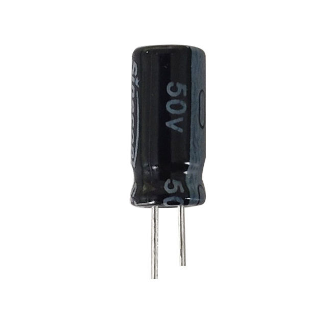
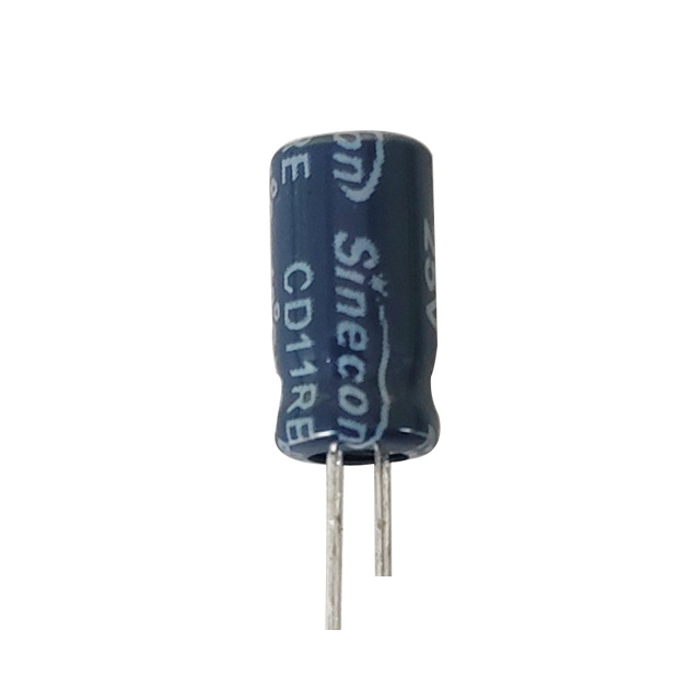
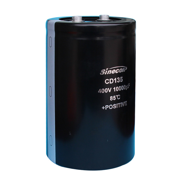
An aluminum capacitor is an electrolytic component built from an etched aluminum foil anode, an oxide dielectric, and a liquid or solid electrolyte — a construction that delivers high capacitance in a small footprint. Under ripple current, however, a film capacitor generally wins: its solid dielectric and low ESR let it shrug off heat that would slowly dry out an aluminum capacitor's electrolyte.
Still, capacitance density tells a different story. An aluminum capacitor packs far more farads into far less volume, which is exactly why it remains the default choice for bulk energy storage and low-to-mid frequency smoothing — anywhere raw capacitance matters more than headroom at high frequency.
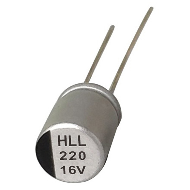
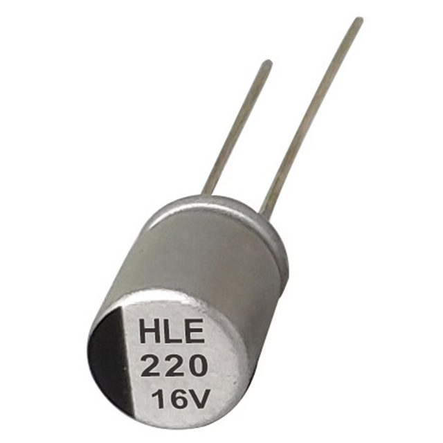
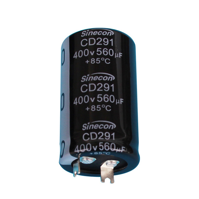
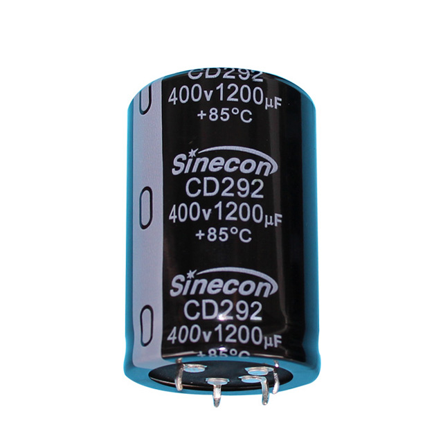
aluminum capacitor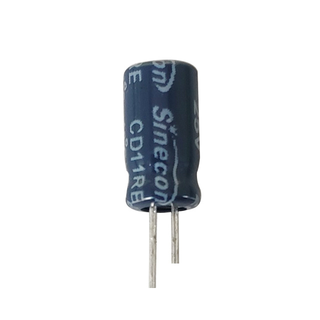
Push the switching frequency past 100 kHz, though, and the gap widens. An aluminum capacitor's ripple rating plateaus; a film capacitor's does not.
Why Ripple Current Is the Real Lifespan Metric
Ripple current is the AC component riding through a capacitor inside a power supply, inverter, or motor drive. It generates heat through the component's ESR, and that heat — more than any other single factor — determines service life.
For an aluminum capacitor, sustained ripple heating accelerates electrolyte evaporation, one of the most common answers to what causes a capacitor to fail in the field. As electrolyte thins, capacitance falls and ESR climbs — a slow, self-reinforcing decline that ends in instability or outright failure.
A film capacitor carries no liquid electrolyte to lose. Its solid polymer dielectric simply doesn't have that failure path — which is the entire reason it tolerates higher ripple at higher temperatures.
Ripple Ratings, Frequency by Frequency
Ripple tolerance isn't a single number — it shifts with frequency, ambient temperature, and case size. The table below compares a mid-capacitance aluminum capacitor against a film capacitor of similar value, both rated at 85°C ambient.
| Frequency | Aluminum Capacitor | Film Capacitor |
| 120 Hz | 100% (baseline) | 100% (baseline) |
| 10 kHz | ~130% | ~180% |
| 100 kHz | ~140% (plateau) | ~250% |
| 500 kHz+ | No further gain | Continues scaling |
The plateau matters. An aluminum capacitor's ripple rating stops improving around 100 kHz, while a film capacitor keeps scaling. That's why high-frequency switching supplies, inverter DC links, and motor-drive snubbers so often lean on film — even at the cost of some capacitance density.
What's Actually Different Inside
Aluminum capacitor — the dielectric is a thin oxide layer grown electrochemically on etched aluminum foil. Etching multiplies surface area, which is how so much capacitance fits into so little space. The electrolyte acts as the true cathode; liquid types carry higher ESR than solid polymer types, which caps ripple handling and drives gradual capacitance loss over time.
Film capacitor — the dielectric is a solid plastic film — polypropylene or polyester — with metal electrodes deposited directly onto it or layered as foil. No electrolyte, no wet chemistry, no drying-out mechanism. ESR stays low and stable across temperature and frequency, which is the structural reason film tolerates far more ripple density without a matching rise in internal heat.
Heat, and the Life It Costs You
Every capacitor has a temperature ceiling, and ripple current is the main thing pushing it there. The industry rule of thumb for an aluminum capacitor: every 10°C rise in core temperature roughly halves usable life. That makes ripple management critical in sealed or airflow-limited enclosures — compact adapters, industrial control cabinets, anything without a fan.
A film capacitor's life-versus-temperature curve is comparatively flat. It doesn't depend on the chemical stability of a liquid electrolyte — its main failure modes are dielectric breakdown or mechanical damage, not thermal evaporation — so it absorbs sustained ripple heating with far less life penalty.
Field Diagnosis: Reading the Warning Signs
An aluminum capacitor pushed past its ripple limit tends to announce itself: a bulging case top, sagging output regulation, or new noise in a switching circuit. A useful first field check is checking capacitor with ohm meter set to resistance or diode-test mode, looking for a short or abnormally low reading that signals dielectric breakdown. It won't measure ESR or true capacitance, but it's a fast way to catch a catastrophic failure before reaching for an ESR meter or LCR bridge.
Info
An ohm meter check is a screening tool, not a substitute for ESR or capacitance measurement — treat a clean reading as inconclusive, not as proof of health.
A film capacitor rarely bulges the same way. It may drift in capacitance gradually or, under transient overstress, self-heal a small dielectric puncture that leaves a mark without an immediate circuit failure — a genuine practical advantage under ripple spikes.
Warning
A visibly bulged or vented aluminum capacitor should be replaced immediately — continued operation risks a rapid, unpredictable failure rather than a gradual one.
Matching the Component to the Circuit
The right choice depends entirely on what the circuit demands:
- Bulk DC bus storage at line frequency — an aluminum capacitor wins on capacitance-per-cost.
- High-frequency switching output filtering — a film capacitor, or a hybrid pairing, handles ripple more gracefully.
- Snubber and DC-link duty in motor drives — film's low ESR and self-healing behavior under repeated transients is the deciding factor.
- Space- and cost-constrained consumer electronics — an aluminum capacitor still makes sense where extreme ripple tolerance isn't the priority.
Success
Pairing a bulk aluminum capacitor with a smaller parallel film capacitor is a common way to combine high capacitance with strong high-frequency ripple absorption.
Extending Ripple Life in Practice
- Choose a ripple rating 20–30% above the calculated requirement for thermal headroom.
- Give the capacitor airflow or a heat sink path — ambient heat compounds ripple-induced self-heating.
- Split the load across several smaller capacitors in parallel rather than one large unit.
- Inspect periodically for case bulging, and use an ohm meter as an early screen.
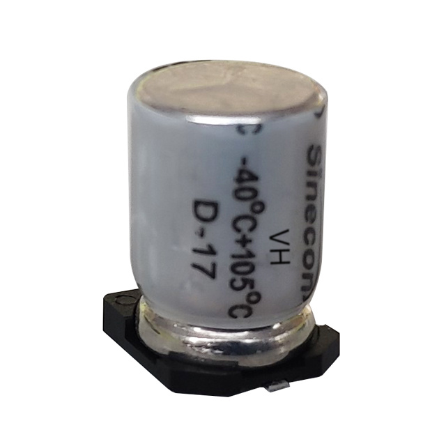
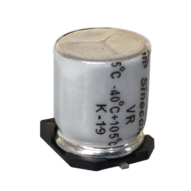
- Where budget allows, a solid polymer aluminum capacitor offers lower ESR and better ripple tolerance than a standard liquid electrolyte type.
Danger
Never exceed a capacitor's rated ripple current to save space or cost — the resulting heat buildup shortens life exponentially, not linearly.
The Takeaway
An aluminum capacitor remains the workhorse for high-capacitance, cost-sensitive designs — but its ripple current handling is fundamentally bound by its electrolyte-based construction and the thermal degradation that comes with it. A film capacitor, with its solid dielectric and low ESR, carries ripple current more gracefully, especially at higher frequencies and temperatures. The best engineering decision is rarely "one or the other" — it's matching each technology to the frequency, thermal, and cost profile of the circuit it needs to serve.