-
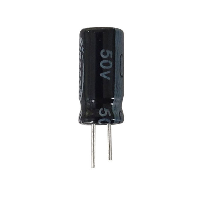
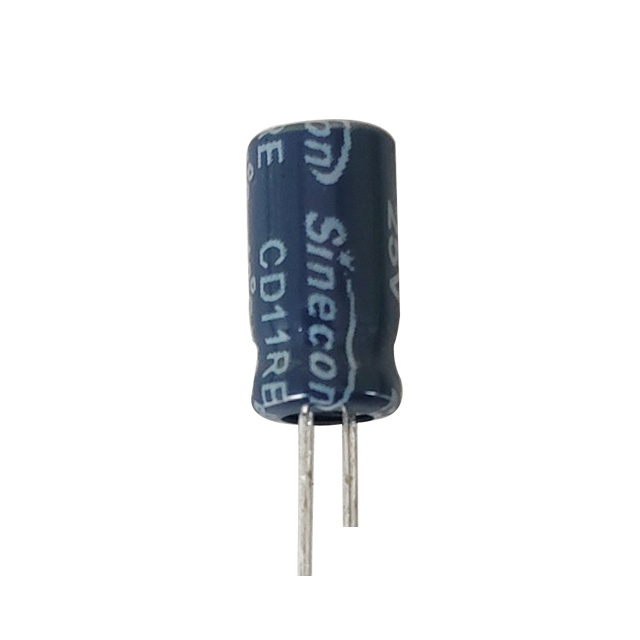
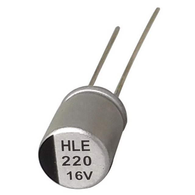
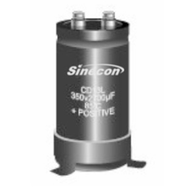
Preferred Orientation for Leakage Prevention — Aluminum Electrolytic Capacitors contain liquid or gel electrolytes that are sensitive to gravity and internal pressure. During operation, chemical reactions within the capacitor generate gas, which is safely vented through the designated pressure relief. Mounting the capacitor vertically with the vent facing upward ensures that this internal gas can escape efficiently, preventing excessive pressure buildup inside the can. If the capacitor is mounted horizontally, the vent may not operate as designed, increasing the likelihood of electrolyte leakage or even case rupture. Vertical mounting reduces the chance of electrolyte pooling against the dielectric surfaces or seals, which can accelerate corrosion or compromise insulation resistance. Following the manufacturer’s orientation guidelines is critical, especially for high-capacitance or high-voltage capacitors, where even minor leakage could affect circuit reliability or safety.
-
Minimizing Mechanical Stress — Mechanical stress on Aluminum Electrolytic Capacitors can come from several sources: lead bending, PCB warping, vibration, or external forces applied to the capacitor body. Stress can damage the internal aluminum foil, dielectric layer, or seals, leading to premature failure. To minimize these risks, the capacitor leads should be inserted into the PCB with proper clearance and without excessive bending near the solder joints. For larger or heavier capacitors, additional mechanical support such as clamps, brackets, or cushioned pads can be used to absorb vibration and prevent oscillatory movement. Proper handling during assembly is also crucial—dropping, twisting, or applying uneven force can compromise the internal construction. Maintaining mechanical stability ensures that the internal connections remain intact and the capacitor operates reliably under both static and dynamic conditions.
-
Thermal Expansion and Heat Management — Aluminum Electrolytic Capacitors generate heat during operation due to ripple currents and dielectric losses. Thermal cycling from environmental temperature variations or operating conditions causes expansion and contraction of the metal case, electrolyte, and internal foil. If the capacitor is tightly constrained, this movement can induce mechanical stress on the leads, solder joints, and PCB, potentially leading to solder fatigue or cracks in the dielectric. To manage thermal expansion, capacitors should have sufficient spacing from nearby components, allow airflow for heat dissipation, and use PCB layouts that accommodate expansion without bending the leads. Derating voltage and ripple current is also critical, as operating capacitors well below their maximum specifications reduces heat generation, prolongs electrolyte life, and minimizes thermal stress. Flexible mounting options, such as cushioned brackets for large capacitors, further mitigate the effects of thermal cycling while maintaining stable electrical connections.
-
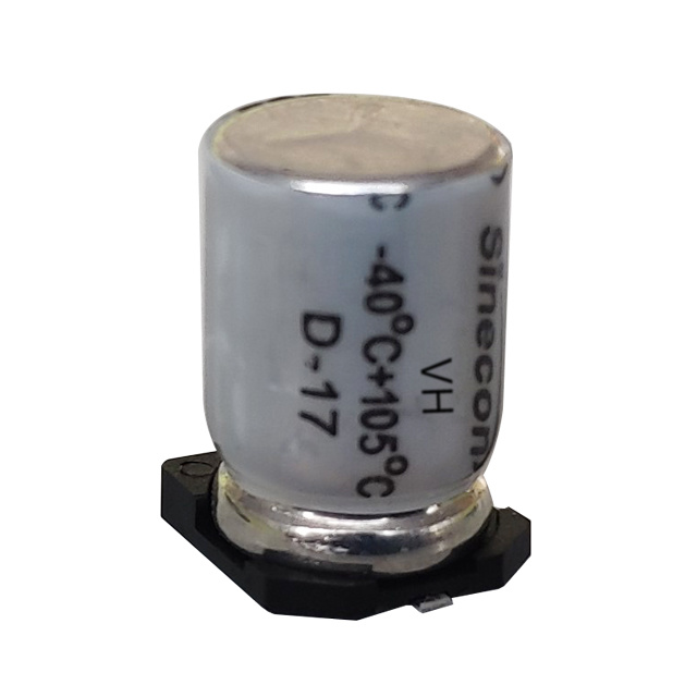
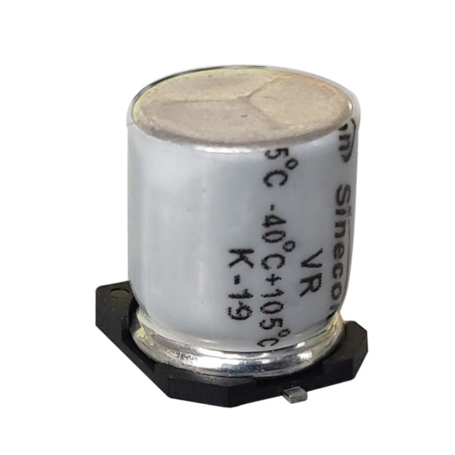
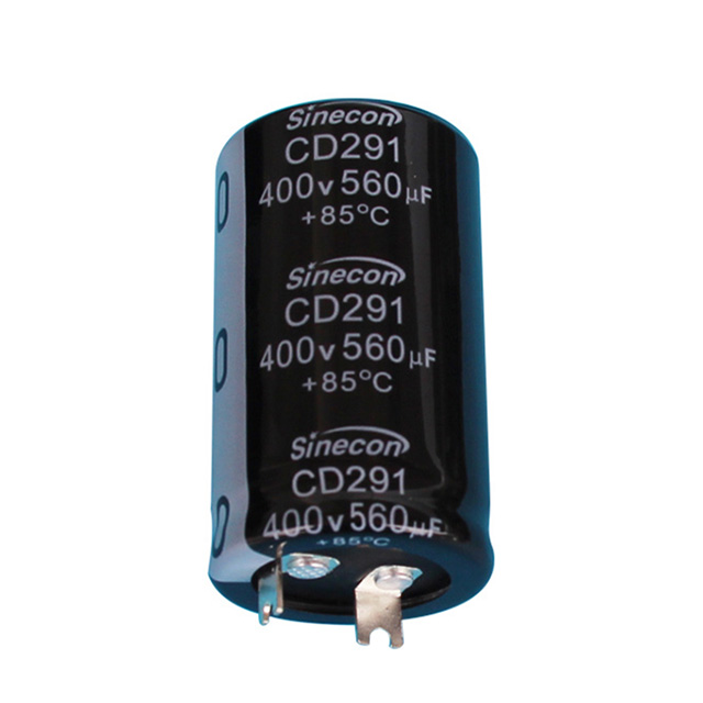
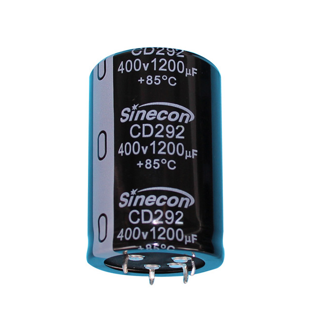
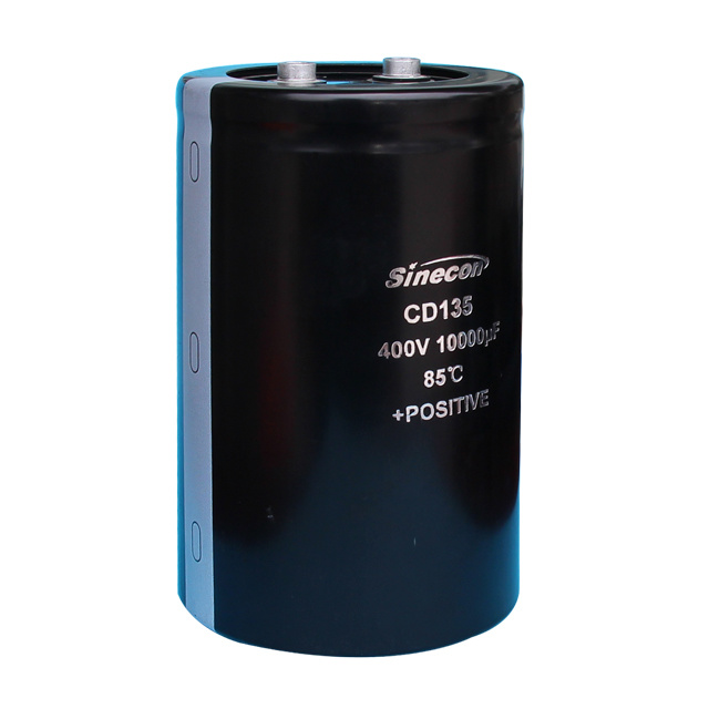
PCB Mounting Best Practices — For through-hole aluminum electrolytic capacitors, correct PCB hole sizing, pad design, and lead alignment are critical to avoid stress during soldering or long-term operation. Leads should not be forced or bent sharply; excessive tension can damage the internal foil. Capacitors should maintain proper creepage and clearance distances, particularly in high-voltage circuits, to avoid leakage or arcing. For surface-mount electrolytic capacitors, orientation and solder pad design must allow venting and accommodate thermal expansion during reflow soldering. Designers should avoid placing heat-generating components directly adjacent to the capacitor to prevent accelerated aging. Proper soldering methods, such as controlled thermal profiles and careful flux application, help maintain reliable mechanical and electrical connections.
-
Environmental Protection and Vibration Considerations — In high-vibration, shock-prone, or outdoor applications, capacitors are exposed to mechanical stress and environmental contaminants. The use of vibration-damping brackets, adhesive supports, or cushioned pads reduces oscillatory movement and prevents solder fatigue. Ensuring that capacitors are not exposed to excessive moisture, dust, or contaminants near the vent prevents corrosion and leakage. Protective coatings on PCB surfaces and adherence to environmental temperature limits are recommended to maintain long-term capacitor reliability.