The aluminum capacitor can be used in a bi-polar (non-polarized) configuration by connecting two units back-to-back — that is, in a series connection with their negative terminals joined together (or alternatively, positive-to-positive). This technique effectively cancels out the polarity requirement of each individual unit, allowing the combined assembly to handle AC signals or circuits where voltage polarity may reverse.
However, this configuration comes with significant performance trade-offs that engineers must carefully evaluate before deployment. It is not a drop-in replacement for a purpose-built non-polarized aluminum capacitor, and understanding the electrical, thermal, and reliability implications is critical for any professional application.
How the Back-to-Back Connection Works
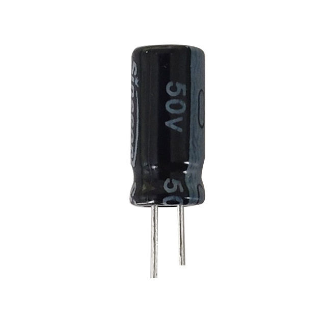
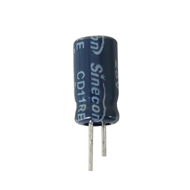
A standard aluminum electrolytic capacitor is polarized, meaning its anode (positive terminal) must always be at a higher potential than its cathode (negative terminal). The electrolytic capacitance of such a component is achieved through an electrochemical oxide layer that is inherently directional — applying reverse voltage, even briefly, can cause electrolyte decomposition, gas generation, and ultimately capacitor failure or rupture.
In a back-to-back configuration, two identical aluminum capacitors are placed in series. The most common wiring method is negative-to-negative (cathode-to-cathode). At any given moment during an AC cycle:
- One aluminum capacitor is forward-biased and actively storing charge.
- The other aluminum capacitor is reverse-biased but protected by its internal oxide layer and the leakage behavior of the forward-biased unit.
The internal oxide layer of an aluminum capacitor can tolerate a small reverse voltage — typically in the range of 1.0 V to 1.5 V — which is sufficient to prevent immediate damage in this balanced configuration. This tolerance is what makes the back-to-back method functional in practice.
Key Performance Trade-Offs to Understand
Using two aluminum capacitors in a back-to-back configuration instead of a single purpose-built non-polarized unit introduces several measurable trade-offs:
Effective Capacitance Is Halved
When two capacitors of equal value C are placed in series, the total electrolytic capacitance is C/2. For example, two 1000 µF / 50 V aluminum capacitors connected back-to-back yield an effective capacitance of only 500 µF. To achieve the target capacitance, you must use units with twice the required value — increasing both cost and board space.
Voltage Rating Is Also Effectively Halved
In a series configuration, the applied voltage is shared between both aluminum capacitors. If each capacitor is rated at 50 V, the combined assembly can handle up to 50 V AC peak — not 100 V. In fact, for safe operation, many engineers apply a derating factor of 20%, meaning two 50 V units back-to-back should be trusted to only 40 V peak AC.
Doubled ESR Resistance and ESL
One of the most critical parameters affected by this configuration is the ESR — Equivalent Series Resistance. The capacitance ESR of a single aluminum capacitor already contributes to energy loss and heat generation during operation. When two units are placed in series, the total ESR resistance of the capacitor assembly doubles, significantly increasing power dissipation. In high-frequency applications such as audio crossovers or switching power supply output filters, where a low ESR capacitor is mandatory, this doubling effect can degrade filtering efficiency at frequencies above 1 kHz and lead to excessive thermal stress. Similarly, Equivalent Series Inductance (ESL) also doubles, further limiting high-frequency performance.
Increased Physical Footprint and Cost
Two aluminum capacitors occupy roughly twice the PCB area and add material cost compared to a single equivalent component. In space-constrained designs, this may be prohibitive.
| Parameter | Single Polarized Aluminum Capacitor | Two Back-to-Back (Same Value) |
|---|---|---|
| Electrolytic Capacitance | C | C / 2 |
| Voltage Rating | V | ~V (shared, derate to 80%) |
| ESR Resistance (Capacitor) | R | 2R |
| ESL | L | 2L |
| Component Count | 1 | 2 |
| AC Suitability | No | Yes |
Practical Applications Where This Configuration Is Used
Despite the trade-offs, the back-to-back aluminum capacitor configuration is a well-established technique in several real-world applications:
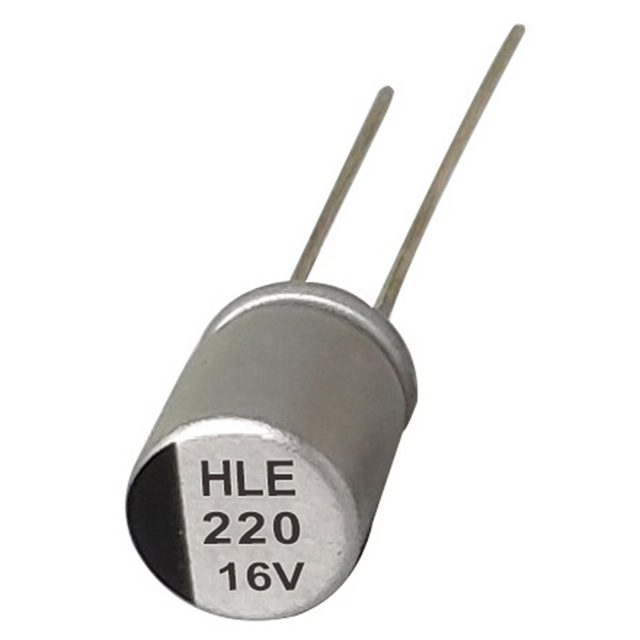
- Audio crossover networks: Passive speaker crossovers require non-polarized capacitors to handle AC audio signals. Two 220 µF aluminum capacitors back-to-back provide a cost-effective 110 µF non-polarized stage for mid-range or woofer filtering, though designers must account for the increased capacitance ESR when calculating insertion loss.
- AC motor starting circuits: Some single-phase AC motor designs use non-polarized capacitors for phase shifting. Back-to-back aluminum capacitors serve as a low-cost alternative when purpose-built motor run capacitors are unavailable.
- Prototyping and lab testing: Engineers often use two standard aluminum capacitors in back-to-back configuration during development phases when purpose-built non-polarized units are not immediately on hand.
- AC coupling stages: In audio amplifier designs where DC bias must be blocked but the signal is AC, this configuration provides a workable solution in low-frequency applications below 10 kHz, provided the ESR capacitor behavior is factored into the signal path analysis.
Design Rules and Best Practices for Back-to-Back Aluminum Capacitors
When implementing this configuration, follow these engineering best practices to maximize reliability and performance:
- Use matched pairs: Always use two aluminum capacitors from the same manufacturer, same series, and same production batch. Mismatched leakage currents can cause uneven voltage sharing, stressing one unit more than the other.
- Select capacitors rated at least twice the target electrolytic capacitance: Since series connection halves the total electrolytic capacitance, start with units of 2C to achieve the desired effective value C.
- Apply voltage derating: Limit operating voltage to no more than 80% of the individual capacitor's voltage rating to account for voltage imbalance and transient spikes.
- Avoid high-frequency applications: Due to the doubled ESR resistance of the capacitor assembly and increased ESL, avoid using this configuration in circuits operating above 10 kHz, such as SMPS output filters or RF bypass applications where a low ESR capacitor is essential.
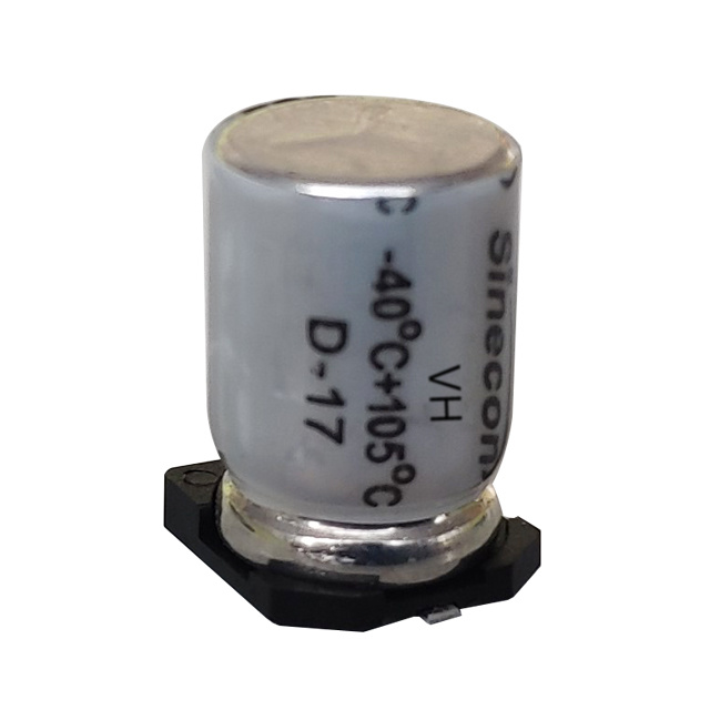
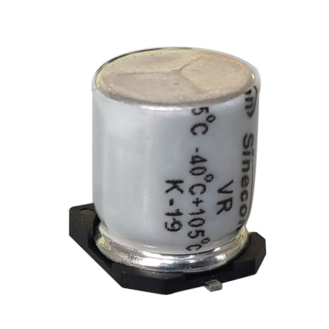
- Monitor operating temperature: Series connection increases total power dissipation, especially given the elevated capacitance ESR of the combined assembly. Ensure thermal management keeps each aluminum capacitor below its rated maximum core temperature — typically 85°C or 105°C depending on the series.
- Consider a bleeder resistor: A high-value resistor (e.g., 100 kΩ) placed across each aluminum capacitor can help equalize voltage distribution and reduce leakage current asymmetry during operation.
When to Use a Purpose-Built Non-Polarized Aluminum Capacitor Instead
While the back-to-back method is valid in many scenarios, there are situations where it is preferable — or mandatory — to use a purpose-built non-polarized aluminum electrolytic capacitor (also called a bipolar electrolytic capacitor):
- When board space is limited and a two-component solution is not feasible.
- When a low ESR capacitor is critical to circuit performance, such as in precision audio circuits or high-efficiency power conversion stages where elevated ESR resistance in the capacitor directly causes measurable signal degradation or thermal runaway.
- When the application demands long-term reliability in harsh environments, such as automotive or industrial systems, where mismatched aging between two separate aluminum capacitors can create unpredictable failure modes.
- When IPC or IEC compliance documentation requires the use of a single, certified component rather than a field-assembled workaround.
Purpose-built bipolar aluminum capacitors are manufactured with oxide layers on both electrodes, providing symmetrical construction, more consistent electrolytic capacitance over time, and more predictable AC performance. They are the preferred choice when design quality and certification are non-negotiable.
The back-to-back aluminum capacitor configuration is a legitimate and widely used engineering technique that enables non-polarized operation from standard polarized components. It is particularly effective in audio applications, motor circuits, and prototyping environments. However, it comes at a cost: effective electrolytic capacitance is halved, the ESR resistance of the capacitor assembly doubles, and careful voltage derating is required.
Engineers should treat this approach as a practical workaround rather than an optimal solution. In applications where capacitance ESR directly impacts efficiency or signal integrity, or where a certified low ESR capacitor is demanded by the design specification, investing in a purpose-built bipolar aluminum capacitor is the more robust and professional choice.