In a Radial Electrolytic Capacitor, the thickness of the dielectric oxide layer has a direct and measurable impact on two critical parameters: voltage rating and capacitance density. Simply put, a thicker oxide layer increases the voltage rating but reduces capacitance per unit volume, while a thinner oxide layer maximizes capacitance density at the cost of lower voltage tolerance. Understanding this trade-off is essential for selecting the right Radial Electrolytic Capacitor for your application.
What Is the Dielectric Oxide Layer in a Radial Electrolytic Capacitor?
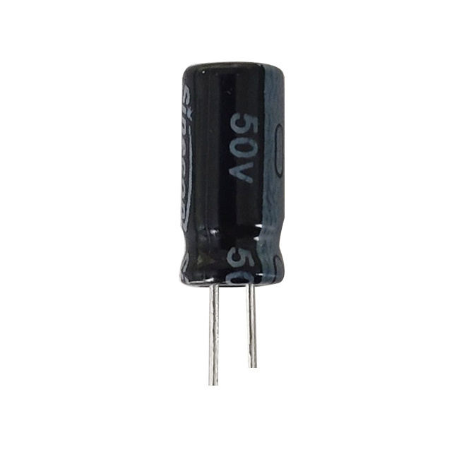
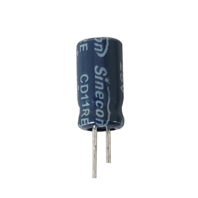
In a standard aluminum Radial Electrolytic Capacitor, the dielectric is a thin layer of aluminum oxide (Al₂O₃) formed by electrochemical anodization on the surface of the aluminum anode foil. This layer acts as the insulating barrier between the anode and the electrolyte (which serves as the cathode).
The formation voltage during manufacturing determines the oxide layer thickness. A commonly used relationship is approximately 1.4 nm of oxide thickness per volt of formation voltage. For example, a capacitor formed at 350V will develop an oxide layer roughly 490 nm thick, while one formed at 10V will have a layer of only about 14 nm.
This thin but highly stable dielectric is what gives the Radial Electrolytic Capacitor its exceptionally high capacitance-to-volume ratio compared to film or ceramic capacitors at equivalent voltage ratings.
How Oxide Layer Thickness Determines Voltage Rating
The breakdown voltage of the dielectric in a Radial Electrolytic Capacitor is directly proportional to the oxide layer thickness. Al₂O₃ has a dielectric strength of approximately 700–1000 V/µm. Manufacturers typically apply a safety margin, rating the capacitor at roughly 70–80% of the actual formation voltage.
For instance, a Radial Electrolytic Capacitor intended for a 25V rating is typically formed at 33–38V to ensure the oxide layer is thick enough to withstand transient overvoltages. A 450V-rated capacitor is formed at around 520–560V, producing an oxide layer approaching 750 nm.
If the applied voltage exceeds the dielectric strength of the oxide layer, irreversible breakdown occurs, often resulting in thermal runaway or catastrophic failure — a critical reason why users must never exceed the rated voltage on a Radial Electrolytic Capacitor.
| Rated Voltage (V) | Typical Formation Voltage (V) | Approx. Oxide Thickness (nm) |
|---|---|---|
| 6.3 | 8–10 | ~11–14 |
| 25 | 33–38 | ~46–53 |
| 100 | 130–140 | ~182–196 |
| 450 | 520–560 | ~728–784 |
How Oxide Layer Thickness Affects Capacitance Density
Capacitance in a Radial Electrolytic Capacitor is governed by the standard parallel plate formula:
C = ε₀ × εᵣ × A / d
Where ε₀ is the permittivity of free space, εᵣ is the relative permittivity of Al₂O₃ (approximately 8–10), A is the effective surface area of the anode foil, and d is the dielectric thickness. Since capacitance is inversely proportional to the dielectric thickness (d), a thinner oxide layer directly produces higher capacitance density.
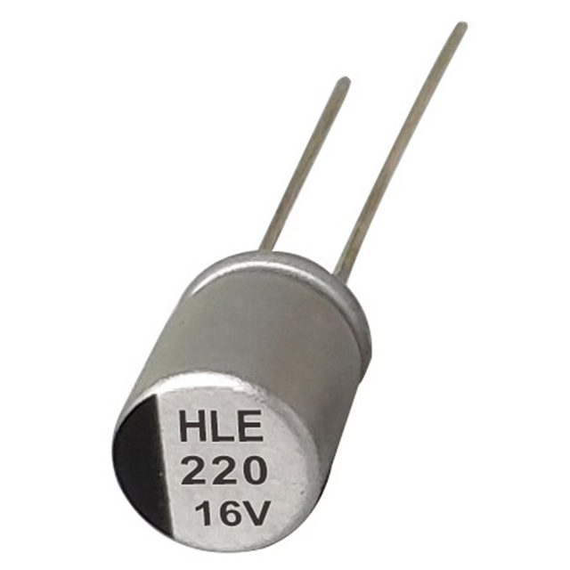
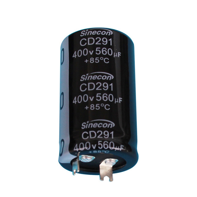
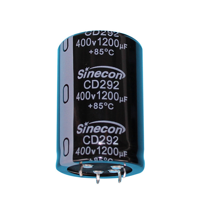
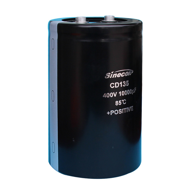
This is why low-voltage Radial Electrolytic Capacitors (e.g., 6.3V or 10V rated) can achieve capacitance values of 1000 µF to 10,000 µF in a compact package, while a 450V-rated Radial Electrolytic Capacitor of the same physical size may only offer 47 µF to 220 µF.
Manufacturers also increase effective surface area through electrochemical etching of the aluminum foil — AC etching for low-voltage types and DC etching for high-voltage types — which can expand the surface area by a factor of 20–100× compared to unetched foil, partially compensating for the capacitance loss from thicker oxide layers in high-voltage designs.
The Engineering Trade-Off: Voltage vs. Capacitance in Radial Electrolytic Capacitor Design
Every Radial Electrolytic Capacitor design involves a fundamental compromise between voltage rating and capacitance density. Engineers and procurement specialists need to understand this when comparing components:
- Higher voltage rating → thicker oxide → lower capacitance per unit volume → larger or more expensive component for the same capacitance.
- Lower voltage rating → thinner oxide → higher capacitance density → smaller, cost-effective component but vulnerable to overvoltage.
- A 1000 µF / 6.3V Radial Electrolytic Capacitor may occupy the same footprint as a 100 µF / 63V Radial Electrolytic Capacitor, illustrating the density penalty imposed by higher voltage requirements.
This trade-off is especially relevant in power supply design, where bulk capacitance on the output rail uses low-voltage, high-capacitance Radial Electrolytic Capacitors, while input-side capacitors handling rectified AC must use high-voltage, lower-capacitance types.
Oxide Layer Quality: Beyond Thickness
The performance of a Radial Electrolytic Capacitor is not determined by oxide layer thickness alone. The uniformity and purity of the Al₂O₃ layer also play a significant role. Defects or contaminants in the oxide can create weak spots, leading to elevated leakage current or premature dielectric breakdown even within the rated voltage range.
Key oxide quality factors include:
- Anodization electrolyte purity: Contaminants during formation increase oxide porosity and raise leakage current in the finished Radial Electrolytic Capacitor.
- Formation temperature control: Temperature variations during anodization affect oxide density and uniformity, impacting both breakdown voltage and long-term stability.
- Re-forming after storage: In stored Radial Electrolytic Capacitors, the oxide layer can partially degrade. Applying a gradually increasing voltage (re-forming) restores the oxide before full operation, especially important for capacitors stored over 2 years without voltage application.
Comparing Radial Electrolytic Capacitor Dielectric Properties to Other Capacitor Types
To put the oxide layer characteristics of a Radial Electrolytic Capacitor in context, it is useful to compare its dielectric properties against competing technologies:
| Capacitor Type | Dielectric Material | Relative Permittivity (εᵣ) | Typical Capacitance Density | Typical Max Voltage |
|---|---|---|---|---|
| Radial Electrolytic Capacitor (Al) | Al₂O₃ | 8–10 | High (up to ~1 F in large cans) | Up to 550V |
| Tantalum Electrolytic Capacitor | Ta₂O₅ | 25–27 | Very High | Up to 50V |
| MLCC (X5R/X7R) | BaTiO₃ ceramic | 1000–4000 | Very High (at low voltage) | Up to 3kV (low C) |
| Film Capacitor (PP) | Polypropylene | 2.2 | Low | Up to 2kV+ |
While tantalum capacitors use Ta₂O₅ with a significantly higher permittivity (~25–27 vs. ~8–10 for Al₂O₃), they are limited to lower voltages. The aluminum Radial Electrolytic Capacitor remains the preferred choice when both high capacitance and voltages above 50V are required simultaneously, thanks to the controllable oxide thickness achievable through aluminum anodization.
Practical Implications for Selecting a Radial Electrolytic Capacitor
When specifying a Radial Electrolytic Capacitor for a design, the following oxide-layer-related considerations should guide your selection:
- Always derate voltage by at least 20%: Operating a Radial Electrolytic Capacitor at or near its rated voltage stresses the oxide layer and accelerates aging. A 25V-rated capacitor should not be used in circuits where voltage can exceed 20V under transient conditions.
- Do not over-specify voltage to save cost: Using a 450V-rated Radial Electrolytic Capacitor in a 12V application wastes board space and budget. The unnecessarily thick oxide layer provides capacitance density far below what the application requires.
- Account for oxide degradation over time: In a Radial Electrolytic Capacitor stored for extended periods, the oxide layer can thin slightly, reducing effective voltage withstand capability. Re-forming procedures should be followed per manufacturer guidelines.
- Consider solid polymer alternatives for low-voltage, high-current applications: Solid polymer Radial Electrolytic Capacitors use a conductive polymer instead of liquid electrolyte, offering lower ESR and longer life, though they share the same oxide-layer-based dielectric mechanism.
The dielectric oxide layer in a Radial Electrolytic Capacitor is not simply an insulating film — it is the core engineering variable that simultaneously defines the component's voltage rating and its capacitance density. With an oxide growth rate of approximately 1.4 nm per formation volt and a dielectric strength of 700–1000 V/µm, the physics are well-understood: thicker oxide = higher voltage rating, lower capacitance density. Selecting the right Radial Electrolytic Capacitor requires balancing these parameters against your circuit's voltage, capacitance, and size requirements — avoiding both under-rating (risk of dielectric breakdown) and over-rating (unnecessary size and cost penalties).